background image

16

INM MTL 130-0126 Rev 13

CALIBRATION 

5.1  General

The MTL katharometer based analysers are extremely stable instruments and require only 
very occasional calibration.  The exact calibration period depends on the type of sample and 
environment the instrument is placed in.  In practice it is unlikely that check periods of less 
than one month would be necessary and three to six months would normally be in order.  We 
recommend that any quality assurance procedures written for the instrument are written to 
allow verification as opposed to calibration.  Verification involves checking that the instrument 
provides the correct analysis of a standard gas within the limits of the instrument and only 
calibrating when a result outside of limits is produced.  The frequency of the verification would 
need to be in line with the quality regime being operated by the user. 

WARNING

The analogue output is set to 2mA (K1650) or 0v (K6050) while the instrument 
is being calibrated.  Ensure that any control loops that are connected to the 
instrument are disabled prior to verifying or calibrating the instrument.  Also 
ensure that the process is in a safe state and the exhaust of the standard gas 
is vented to a safe area.  Calibration mode can only be entered by pressing the 
Calibrate button for approximately 8 seconds whilst in Measurement Mode.

5.2  Piping

Ensure that the piping and connectors are of good quality with no possibility of leaks.   Metal 
piping is preferred as it is less prone to damage and sealing problems.  Pressure regulators and 
gauges that may be in the calibration gas lines all have a certain amount of dead space within 
them and so may require purging for several minutes before the delivered gas matches that of 
the cylinder contents.  The regulator etc. may be connected to the instrument and the purge 
monitored by using the instrument in measurement mode.  Only when the reading is steady 
has the dead space been purged.  
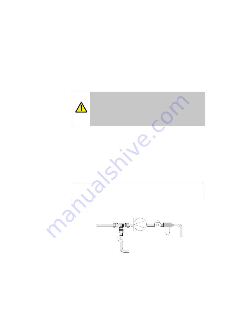
NOTE

For permanent installations (K1650) in may be convenient to include a ‘T’ piece and 

appropriate valves in the sample inlet line so that the calibration gas is easily connected.

Figure 11 

- Sample and calibration gas piping

Calibration

Gas Inlet

To Process

Sample Connection

To Sample Inlet

Filter

Shut-off

Valve

Pump

-if required

Shut-off

Valve

Summary of Contents for K1650

Page 1: ...K1650 K6050 MTL alternator purge gas analysers January 2017 INM MTL 130 0126 Rev 13 Instruction manual MTL gas analysers systems...

Page 2: ...CLARATION OF CONFORMITY A printed version of the Declaration of Conformity has been provided separately within the original shipment of goods However you can find a copy of the latest version at http...

Page 3: ...3 1 K1650 4 3 3 2 K6050 4 3 3 3 Routing of wires 4 3 4 Sampling and piping 5 3 5 Flow meter 8 3 5 1 K6050 8 3 5 2 K1650 8 3 6 Electronic module installation K1650 8 3 7 Sensor and control display unit...

Page 4: ...iv INM MTL 130 0126 Rev 13 THIS PAGE IS LEFT INTENTIONALLY BLANK...

Page 5: ...based core which provides a fully featured yet easy to use gas analyser Gas analysis takes place using thermal conductivity measurements made using a highly stable non depleting katharometer sensor Th...

Page 6: ...bsolute maximum 6 Bar Operating For stated accuracy the sample outlet should be at atmospheric pressure 2 9 Sample condition Must be non condensing and free of particulates 2 10 Sample connections Sta...

Page 7: ...0 80 RH non condensing Storage temperature range K6050 20 C to 55 C K1650 instrument 20 C to 50 C sensor 20 C to 60 C 0 80 RH non condensing Altitude Up to 2000m Pollution degree Pollution degree 2 2...

Page 8: ...instrument mounted in a rugged case See Figure 4 Ensure that the environmental requirements of Section 2 13 are met 3 3 Electrical connections 3 3 1 K1650 Three plug in terminal blocks are provided a...

Page 9: ...sample outlet NOTE Optimum analyser performance is achieved with the flow rate specified in Section 4 7 Consider also installing pipe work for a calibration gas inlet this avoids the need to remove t...

Page 10: ...O2 Range Alarm CO in Air 2 Alarm NO NO NO C C C COM REF SIG REMOTE SENSOR M5 mounting studs x 6 at rear of panel 16mm length Cutout required in mounting surface 186 x 138mm centred 160 192 100 100 240...

Page 11: ...1 2 3 4 18 View Edit Cal Meas Cal Gas HITECH INSTRUMENTS Tapped M20 entries Tapped M20 entry 82 270 318 14 310 353 490 65 50 50 50 55 270 98 20 Dimensions in mm View Edit Cal Meas Cal Gas 2 L A 2 L A...

Page 12: ...rther details 3 7 Sensor and control display unit connections CAUTION The sensor and control unit are matched during manufacture Each instrument will operate correctly only with its own sensor The sen...

Page 13: ...18 16 4 3 2 1 6 5 20 19 Live Neutral Earth Alarm1 NO Alarm 1 C Alarm 1 NC Alarm 2 NO Alarm 2 C Alarm 2 NC 4 20mA 4 20mA 120 0430 2 IP65 Keyboard Box containing Simple Apparatus Switches Ex d IP66 Cab...

Page 14: ...the K1650 control display unit Ensure that supplies are isolated at some external point before working on connections to the unit CAUTION Check the supply voltage rating of the control unit before con...

Page 15: ...s see Figure 3 They must be fitted with appropriately certified cable glands or similarly approved blanking plugs for any unused ones Only one cable can be passed through a cable gland so four holes a...

Page 16: ...ils of the instrument s name and software number This display will remain for a few moments then the instrument will automatically enter Measurement Mode and set itself to Range 3 hydrogen in air The...

Page 17: ...the selected range is shown at the bottom of the display Using a combination of the H2 in CO2 Range relay and the CO2 inAir Range relay it is possible to monitor externally which of the three ranges h...

Page 18: ...character of the parameter to be edited Use the or buttons to change the digit to that required and then use the Edit button to move the cursor to the next digit to be changed When the View button is...

Page 19: ...in the CO2 in air range 2 Indicates fault while instrument is in the H2 in CO2 range 4 Indicates fault while instrument is in the H2 in air range 8 Temperature channel A D reading out of range low 16...

Page 20: ...e disabled prior to verifying or calibrating the instrument Also ensure that the process is in a safe state and the exhaust of the standard gas is vented to a safe area Calibration mode can only be en...

Page 21: ...2 level is high approaching 100 system is pressurised to a higher pressure we will refer to it as y barg The following assumptions are made in advising this alternative calibration process The 0 to 10...

Page 22: ...ir cal for CO cal VIEW to exit 2 for H cal 2 Pass 100 CO2 CO2 MEAS When ready VIEW to exit Pass 100 H2 H2 MEAS When ready VIEW to exit Calibration error Reading too high VIEW to continue Calibration e...

Page 23: ...n an instrument it is important that the serial number is quoted This will be found on the data label attached to the instrument 6 1 Battery replacement K6050 analysers contain a NiMH battery which is...

Page 24: ...rozavodskaya Str 33 Building 4 Moscow 107076 Russia Tel 7 495 981 3770 Fax 7 495 981 3771 E mail mtlrussia eaton com SINGAPORE Cooper Crouse Hinds Pte Ltd No 2 Serangoon North Avenue 5 06 01 Fu Yu Bui...

Reviews: