


Spring release kit in
IZM low voltage circuit breakers
Eaton Industries GmbH
Electrical Sector
©2010 by Eaton Industries GmbH
Änderungen vorbehalten
Subject to alterations
05/10 AWA1230-2442 / Z8692
Moon/Doku/Heng
Printed in USA (05/10)
05/10 AWA1230-2442
Effective May 2010
Figure 2. Step 3
cautiOn
becOme familiar with this cautiOn On pOlarity befOre
prOceeding with steps 4 Or 5. failure tO apply the cOrrect
pOlarity will result in damage tO the device.
Step 4:
For a breaker
without
an 1150 trip unit
, connect wires
from spring release to secondary contact block “B” in keeping
with markings on wires. If the breaker has an 1150 trip unit, skip
this step and proceed directly to Step 5.
Mounting
Plate
Hook Feet
Forward
Spring
Release
Lock
Spring Release
Mounts Only In
Middle Slot
When connecting a 24 Vdc or 48 Vdc Spring
Release Device, be certain to apply positive (+)
voltage to the secondary terminal “B12.”
For a breaker with an 1150 trip unit and a
24 Vdc or 48 Vdc Spring Release Device, be
certain to apply positive voltage to secondary
terminal “A13” for INCOM Close.
SR
B12
B13
DC Pos. (+)
DC Neg. (–)
INCOM
Close
A13
DC Pos. (+)
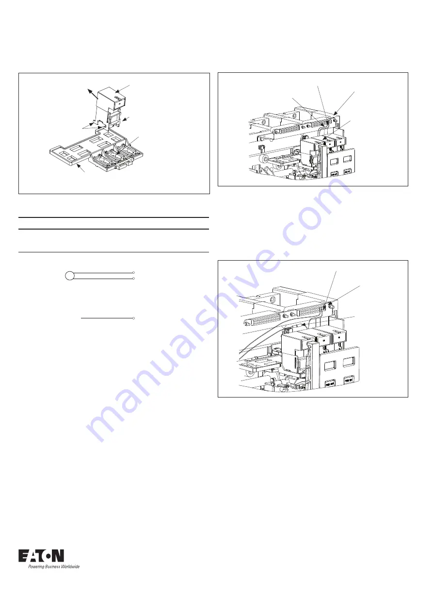
Figure 3. Step 4
Step 5:
For a breaker
with
an 1150 trip unit only, find the rust-
colored connector in the vicinity of where the spring release
device is mounted. This two-piece connector will easily separate
by pulling apart on the two ends. Insert the spring release
wire marked “B12” into the connector until it snaps into place.
Re-connect the rust-colored connector. Insert the spring release
wire “B13” into the breaker secondary block “B” at position 13.
Figure 4. Step 5
Step 6:
Reinstall front cover removed in Step 1.
Spring
Release
Secondary
Block “B”
Position 12
Position 13
Rust-Colored
Connector
Secondary
Block “B”
Position 13


