background image

Page 14

SK-90610-Y4_EN

5. Operations

UPS

BYPASS

UPS

BYPASS

5.1 UPS start-up with HotSwap MBP


Verify that the total equipment ratings do not exceed the UPS capacity to prevent an overload alarm.

1. Check that the UPS is correctly connected to the HotSwap MBP (see previous chapter 4)


 If the UPS if equipped with outlets

, those outlets can no longer be used (loads can only be connected to the 

MBP outlets or the MBP Output terminal blocks).

2. Verify that the MBP terminal blocks are connected to the AC source.

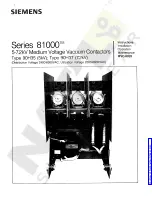
3. Check that the MBP manual Bypass switch is to the 

"Bypass" position

.

4.  Set the upstream circuit breaker (not provided) to the "I" position (On) to switch On the utility power.
5.  Verify that the 

"Bypass mode" red light

 of the MBP goes On, indicating that the load is now powered by 

the AC source.

6. Set the Normal AC source switch of the MBP to the "I" position.
7. Verify that the UPS is correctly powered (UPS display panel illuminates).
8. Press the UPS 

"ON"

 button to start the UPS.

9. Put the UPS in 

"internal Bypass mode" 

(refer to the UPS User Manual). 

10. Verify that the UPS is on Bypass mode by checking UPS display panel (refer to the UPS user manual).
11.  Verify that the 

"UPS mode" green light

 of the MBP goes On, indicating that the UPS output power is 

available on the MBP.


Important:

  do not continue to next step if the 

"UPS mode" green light

 of the MBP is still Off  

(the load will be lost).

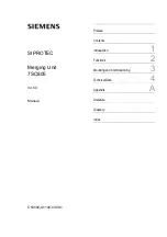
12.  Set the MBP manual Bypass switch to the 

"UPS" position

: the 

"Bypass mode" red light 

of the MBP goes 

Off, indicating that the load is now powered by the UPS.

13. Put the UPS in "

normal mode

" (refer to the UPS User Manual).

14.  Check that the UPS is in Online mode by checking UPS display panel (refer to the UPS user manual)  

the load is now protected by the UPS.

Summary of Contents for HotSwap MBP Series

Page 1: ...ENGLISH HotSwap MBP Maintenance Bypass MBP6K208 MBP11K208 Installation and user manual Copyright 2012 EATON All rights reserved Service and support Call your local service representative SK 90610 Y4_EN ...

Page 2: ... found to comply with Class A UPS pursuant to Part 15 of the FCC Rules These limits are designed to provide reasonable protection against harmful interference when the equipment is operated in a commercial environment This equipment generates uses and can radiate radio frequency energy and if not installed and used in accordance with the instruction manual may cause harmful interference to radio c...

Page 3: ...e ANSI NFPA 70 US installations only The upstream circuit breaker must be easily accessible The unit can be disconnected from AC power source by opening this circuit breaker and if still connected to UPS by previously shutting down the UPS refer to the UPS User Manual p p Check that the indications on the rating plate correspond to your AC powered system and to the actual electrical consumption of...

Page 4: ...ecting the equipment 9 3 2 Unpacking the MBP 9 3 3 Checking the accessory kit 9 3 4 Mechanical Mounting 10 3 5 Installation requirements 10 4 Power cables connection 11 4 1 MBP6K208 11 4 2 MBP11K208 12 5 Operations 14 5 1 UPS start up with HotSwap MBP 14 5 2 UPS replacement with HotSwap MBP 15 5 3 UPS maintenance with HotSwap MBP 17 6 Specifications 18 Contents ...

Page 5: ...improve waste treatment and facilitate recycling separate the various packing components p p The cardboard we use comprises over 50 of recycled cardboard p p Sacks and bags are made of polyethylene p p Packing materials are recyclable and bear the appropriate identification symbol 01 PET Materials Abbreviations Number in 01 PET the symbols Polyethylene terephthalat PET 01 High density polyethylene...

Page 6: ...connector Hotswap MBP 5 6kVA range p p make before break feature to allow full servicing electrical power continuity when switching from UPS position to Bypass and vice versa p p Communication feature with UPS detection of MBP connection and switch position Normal or Bypass works only with some approved EATON UPS contact your Eaton reseller for more information p p Load connection by both terminal...

Page 7: ...sentation MBP11K208 Tower installation Rack installation Wall mounting Description Weight lb kg Dimensions inch mm D x W x H MBP6K208 5 5 2 5 4 3 x 7 0 x 5 1 110 x 177 x 130 MBP11K208 13 7 6 2 8 7 x 13 2 x 5 1 220 x 336 x 130 D W H D W H ...

Page 8: ...signal cable with RJ11 connector to plug to the UPS allows the communication to the UPS to manage the MBP status and the indication on UPS display panel of both following status p p MBP connection to UPS p p Bypass switch position Check the UPS user manual to check the compatibility of this feature or contact Eaton reseller for more information MBP6K208 5 3 4 1 6 7 2 MBP11K208 6 1 4 3 2 9 8 5 7 1 ...

Page 9: ...s free of humidity flammable gas and corrosion Packing materials must be disposed of in compliance with all local regulations concerning waste Recycling symbols are printed on the packing materials to facilitate sorting 3 3 Checking the accessory kit p p Verify that the following additional items are included with the MBP MBP6K208 1 2 5 3 6 4 1 Input Output UPS cord set 2 2 cable glands 3 Rack kit...

Page 10: ... upstream the MBP Normal AC source 2 Recommended cable cross sections 3 Installation Terminal position Wire function Terminal wire size rating Minimum input wire size rating Tightening torque MBP6K208 L1 Phase 0 5 10 mm2 20 8 AWG 6 mm2 10 AWG 105 C 10 mm2 8 AWG 75 C 10 lb in L2 Phase Ground MBP11K208 with 8kVA UPS L1 Phase 4 25 mm2 12 4 AWG 10 mm2 8 AWG 105 C 16 mm2 6 AWG 75 C 18 lb in L2 Phase Gr...

Page 11: ... terminal blocks connection 3 Connect the MBP detection cable from the I O cord Set 1 to the specific UPS connector MBP detect refer to UPS User Manual Only with compatible EATON UPS contact your Eaton reseller for more information 4 Slide the MBP I O cover 2 after removing the 4 screws to access to MBP terminal blocks 5 Punch the knockouts and insert the provided cable glands inside 6 Insert the ...

Page 12: ...2 and secure it with 3 screws 9 Remove the I O terminal blocks cover of the UPS refer to the UPS user manual 10 Punch the Input and Output knockouts of the UPS I OTB cover and insert 2 provided conduit fittings inside 11 Insert the conduits 3 and 4 through the previously mounted conduit fittings of the UPS I OTB cover following color coding on the conduits and the UPS I OTB cover blue for UPS Inpu...

Page 13: ...AC source Input terminal blocks of MBP 19 Insert the Output cable through the cable gland or a conduit through the conduit fitting 20 Connect the wires to the Output terminal blocks of MBP 21 Put back the MBP I O cover 1 and secure it with 4 screws on the MBP casing 22 Put back the top cover 5 of the MBP I O cover 1 and secure it with 3 screws 23 Tighten the cable glands if used instead of conduit...

Page 14: ... now powered by the AC source 6 Set the Normal AC source switch of the MBP to the I position 7 Verify that the UPS is correctly powered UPS display panel illuminates 8 Press the UPS ON button to start the UPS 9 Put the UPS in internal Bypass mode refer to the UPS User Manual 10 Verify that the UPS is on Bypass mode by checking UPS display panel refer to the UPS user manual 11 Verify that the UPS m...

Page 15: ...ce 4 Switch the Normal AC source switch of the MBP to the 0 position and wait 30 seconds 5 UPS stops the UPS can now be disconnected as described below p p First disconnect the I O cord Set 1 from the MBP after removing the 2 screws 1 p p After opening the UPS I O terminal blocks cover check if hazardous voltage is no longer present on UPS terminal blocks by using an electrical safety tester p p D...

Page 16: ...cted as described below p p First lock the Normal AC source switch 3 of the MBP to the 0 position the switch protection frame is able to fit a cable tie or a metallic locker 3 p p After opening the I O terminal blocks cover of UPS check if hazardous voltage is no longer present on UPS terminal blocks by using an electrical safety tester p p Disconnect the MBP conduits and the MBP detection cable f...

Page 17: ...ght of the MBP is still Off the load will be lost 8 Set the MBP manual Bypass switch to the UPS position the Bypass mode red light of the MBP goes Off indicating that the load is now powered by the UPS 9 Put the UPS in normal mode refer to the UPS User Manual 10 Check that the UPS is in Online mode by checking UPS display panel refer to the UPS user manual the load is now protected by the UPS 5 3 ...

Page 18: ... 2011 ESD IEC 61000 4 2 level 3 Radiated field IEC 61000 4 3 level 3 EFT IEC 61000 4 4 level 4 Fast transients IEC 61000 4 5 level 4 Electromagnetic field IEC 61000 4 6 level 3 Conducted magnetic field IEC 61000 4 8 level 4 Marking cULus Listed CE Environment Operating temperature 0 to 40 C 32 to 104 F Storage temperature 15 to 60 C 5 to 140 F Transit temperature 25 to 55 C 13 to 130 F Humidity 0 ...

Reviews: