background image

1

Installation Guide: EV wall charger and EV wall charger plug-in

EV WALL CHARGER AND EV WALL CHARGER PLUG-IN

   www.eaton.com

Contents

PRODUCT INTRODUCTION

   .  .  .  .  .  .  .  .  .  .  .  .  .  .  .  .  .  .  .  .  .  .  .  .  .  .  .  .  .  .  .  .  .  .  .  .  .  .  .  .  .  .  .  .  .  .  .  .  .  .  .  .  .  .  .  .  .  .  .  .  .  .  .  .  .  .  .  .  .  .  .  .

2–3

EV wall charger (hardwire, plug-in, or pedestal options) .    .  .  .  .  .  .  .  .  .  .  .  .  .  .  .  .  .  .  .  .  .  .  .  .  .  .  .  .  .  .  .  .  .  .  .  .  .  .  .  .  .  .  .  .  .  .  .  .  .

2

EV smart breaker charger   .  .  .  .  .  .  .  .  .  .  .  .  .  .  .  .  .  .  .  .  .  .  .  .  .  .  .  .  .  .  .  .  .  .  .  .  .  .  .  .  .  .  .  .  .  .  .  .  .  .  .  .  .  .  .  .  .  .  .  .  .  .  .  .  .  .  .  .  .  .  .  .  .

3

PACKAGE CONTENTS

   .  .  .  .  .  .  .  .  .  .  .  .  .  .  .  .  .  .  .  .  .  .  .  .  .  .  .  .  .  .  .  .  .  .  .  .  .  .  .  .  .  .  .  .  .  .  .  .  .  .  .  .  .  .  .  .  .  .  .  .  .  .  .  .  .  .  .  .  .  .  .  .  .  .  .  .  .  .  .

4

EV wall charger  .   .  .  .  .  .  .  .  .  .  .  .  .  .  .  .  .  .  .  .  .  .  .  .  .  .  .  .  .  .  .  .  .  .  .  .  .  .  .  .  .  .  .  .  .  .  .  .  .  .  .  .  .  .  .  .  .  .  .  .  .  .  .  .  .  .  .  .  .  .  .  .  .  .  .  .  .  .  .  .  .

4

EV wall charger plug-in  .    .  .  .  .  .  .  .  .  .  .  .  .  .  .  .  .  .  .  .  .  .  .  .  .  .  .  .  .  .  .  .  .  .  .  .  .  .  .  .  .  .  .  .  .  .  .  .  .  .  .  .  .  .  .  .  .  .  .  .  .  .  .  .  .  .  .  .  .  .  .  .  .  .  .

4

ROUTINE OPERATION

   .  .  .  .  .  .  .  .  .  .  .  .  .  .  .  .  .  .  .  .  .  .  .  .  .  .  .  .  .  .  .  .  .  .  .  .  .  .  .  .  .  .  .  .  .  .  .  .  .  .  .  .  .  .  .  .  .  .  .  .  .  .  .  .  .  .  .  .  .  .  .  .  .  .  .  .

5–6

EV smart breaker charger operation  .   .  .  .  .  .  .  .  .  .  .  .  .  .  .  .  .  .  .  .  .  .  .  .  .  .  .  .  .  .  .  .  .  .  .  .  .  .  .  .  .  .  .  .  .  .  .  .  .  .  .  .  .  .  .  .  .  .  .  .  .  .  .  .  .

5

LED indicator descriptions .   .  .  .  .  .  .  .  .  .  .  .  .  .  .  .  .  .  .  .  .  .  .  .  .  .  .  .  .  .  .  .  .  .  .  .  .  .  .  .  .  .  .  .  .  .  .  .  .  .  .  .  .  .  .  .  .  .  .  .  .  .  .  .  .  .  .  .  .  .  .  .  .

6

INSTALLATION

   .  .  .  .  .  .  .  .  .  .  .  .  .  .  .  .  .  .  .  .  .  .  .  .  .  .  .  .  .  .  .  .  .  .  .  .  .  .  .  .  .  .  .  .  .  .  .  .  .  .  .  .  .  .  .  .  .  .  .  .  .  .  .  .  .  .  .  .  .  .  .  .  .  .  .  .  .  .  .  .  .  .

7–26

Safety information  .   .  .  .  .  .  .  .  .  .  .  .  .  .  .  .  .  .  .  .  .  .  .  .  .  .  .  .  .  .  .  .  .  .  .  .  .  .  .  .  .  .  .  .  .  .  .  .  .  .  .  .  .  .  .  .  .  .  .  .  .  .  .  .  .  .  .  .  .  .  .  .  .  .  .  .  .  .  .

7

General reference   .  .  .  .  .  .  .  .  .  .  .  .  .  .  .  .  .  .  .  .  .  .  .  .  .  .  .  .  .  .  .  .  .  .  .  .  .  .  .  .  .  .  .  .  .  .  .  .  .  .  .  .  .  .  .  .  .  .  .  .  .  .  .  .  .  .  .  .  .  .  .  .  .  .  .  .  .  .  .

8

EV wall charger and EV wall charger plug-in installation   .  .  .  .  .  .  .  .  .  .  .  .  .  .  .  .  .  .  .  .  .  .  .  .  .  .  .  .  .  .  .  .  .  .  .  .  .  .  .  .  .  .  .  .  .  .  .

9–15

• 

A - Prepare the EV wall charger   .  .  .  .  .  .  .  .  .  .  .  .  .  .  .  .  .  .  .  .  .  .  .  .  .  .  .  .  .  .  .  .  .  .  .  .  .  .  .  .  .  .  .  .  .  .  .  .  .  .  .  .  .  .  .  .  .  .  .  .  .  .

9–11

• 

B - Mount the EV wall charger   .  .  .  .  .  .  .  .  .  .  .  .  .  .  .  .  .  .  .  .  .  .  .  .  .  .  .  .  .  .  .  .  .  .  .  .  .  .  .  .  .  .  .  .  .  .  .  .  .  .  .  .  .  .  .  .  .  .  .  .  .  .  .  .  .

12

• 

C - Connect conduit collet   .  .  .  .  .  .  .  .  .  .  .  .  .  .  .  .  .  .  .  .  .  .  .  .  .  .  .  .  .  .  .  .  .  .  .  .  .  .  .  .  .  .  .  .  .  .  .  .  .  .  .  .  .  .  .  .  .  .  .  .  .  .  .  .  .  .  .  .

13

• 

D - Wire EV wall charger and install EV wall charger front cover  .  .  .  .  .  .  .  .  .  .  .  .  .  .  .  .  .  .  .  .  .  .  .  .  .  .  .  .  .  .  .  .  .  .  .  .

14–15

EV wall charger pedestal installation  .  .  .  .  .  .  .  .  .  .  .  .  .  .  .  .  .  .  .  .  .  .  .  .  .  .  .  .  .  .  .  .  .  .  .  .  .  .  .  .  .  .  .  .  .  .  .  .  .  .  .  .  .  .  .  .  .  .  .  .  .

16–26

• 

A - Prepare EV pedestal   .  .  .  .  .  .  .  .  .  .  .  .  .  .  .  .  .  .  .  .  .  .  .  .  .  .  .  .  .  .  .  .  .  .  .  .  .  .  .  .  .  .  .  .  .  .  .  .  .  .  .  .  .  .  .  .  .  .  .  .  .  .  .  .  .  .  .

16–17

• 

B - Install EV wall charger base   .  .  .  .  .  .  .  .  .  .  .  .  .  .  .  .  .  .  .  .  .  .  .  .  .  .  .  .  .  .  .  .  .  .  .  .  .  .  .  .  .  .  .  .  .  .  .  .  .  .  .  .  .  .  .  .  .  .  .  .  .

18–20

• 

C - Run wiring through EV pedestal  .  .  .  .  .  .  .  .  .  .  .  .  .  .  .  .  .  .  .  .  .  .  .  .  .  .  .  .  .  .  .  .  .  .  .  .  .  .  .  .  .  .  .  .  .  .  .  .  .  .  .  .  .  .  .  .  .  .  .  .  .

21

• 

D - Replace cover plate(s)    .  .  .  .  .  .  .  .  .  .  .  .  .  .  .  .  .  .  .  .  .  .  .  .  .  .  .  .  .  .  .  .  .  .  .  .  .  .  .  .  .  .  .  .  .  .  .  .  .  .  .  .  .  .  .  .  .  .  .  .  .  .  .  .  .

22–23

• 

E - Install second EV wall charger base   .  .  .  .  .  .  .  .  .  .  .  .  .  .  .  .  .  .  .  .  .  .  .  .  .  .  .  .  .  .  .  .  .  .  .  .  .  .  .  .  .  .  .  .  .  .  .  .  .  .  .  .  .  .  .  .  .  .

24

• 

F - Run wiring through EV pedestal   .  .  .  .  .  .  .  .  .  .  .  .  .  .  .  .  .  .  .  .  .  .  .  .  .  .  .  .  .  .  .  .  .  .  .  .  .  .  .  .  .  .  .  .  .  .  .  .  .  .  .  .  .  .  .  .  .  .  .  .  .

25

• 

G - Install cord hook and lower access cover    .  .  .  .  .  .  .  .  .  .  .  .  .  .  .  .  .  .  .  .  .  .  .  .  .  .  .  .  .  .  .  .  .  .  .  .  .  .  .  .  .  .  .  .  .  .  .  .  .  .

26–27

• 

H - Wire EV wall charger and install EV wall charger front cover  .  .  .  .  .  .  .  .  .  .  .  .  .  .  .  .  .  .  .  .  .  .  .  .  .  .  .  .  .  .  .  .  .  .  .  .

28–29

FCC

   .  .  .  .  .  .  .  .  .  .  .  .  .  .  .  .  .  .  .  .  .  .  .  .  .  .  .  .  .  .  .  .  .  .  .  .  .  .  .  .  .  .  .  .  .  .  .  .  .  .  .  .  .  .  .  .  .  .  .  .  .  .  .  .  .  .  .  .  .  .  .  .  .  .  .  .  .  .  .  .  .  .  .  .  .  .  .  .  .  .  .  .  .  .  .

30 

CONNECT TO WI-FI

   .  .  .  .  .  .  .  .  .  .  .  .  .  .  .  .  .  .  .  .  .  .  .  .  .  .  .  .  .  .  .  .  .  .  .  .  .  .  .  .  .  .  .  .  .  .  .  .  .  .  .  .  .  .  .  .  .  .  .  .  .  .  .  .  .  .  .  .  .  .  .  .  .  .  .  .  .  .  .  .

31 

TECHNICAL SPECIFICATIONS

   .  .  .  .  .  .  .  .  .  .  .  .  .  .  .  .  .  .  .  .  .  .  .  .  .  .  .  .  .  .  .  .  .  .  .  .  .  .  .  .  .  .  .  .  .  .  .  .  .  .  .  .  .  .  .  .  .  .  .  .  .  .  .  .  .  .  .  .  .  .  .

32

TROUBLESHOOTING

   .  .  .  .  .  .  .  .  .  .  .  .  .  .  .  .  .  .  .  .  .  .  .  .  .  .  .  .  .  .  .  .  .  .  .  .  .  .  .  .  .  .  .  .  .  .  .  .  .  .  .  .  .  .  .  .  .  .  .  .  .  .  .  .  .  .  .  .  .  .  .  .  .  .  .  .  .  .  .

33

Summary of Contents for EV wall charger

Page 1: ...Installation guide EV wall charger and wall charger plug in Green Motion EV smart breaker chargers ...

Page 2: ...Fault Ready Active U S T Y P E 3 R IP 5 4 S A E J 1 7 7 2 TM Fault Ready Active U S T Y P E 3 R IP 5 4 S A E J 1 7 7 2 TM ...

Page 3: ...harger and EV wall charger plug in installation 9 15 A Prepare the EV wall charger 9 11 B Mount the EV wall charger 12 C Connect conduit collet 13 D Wire EV wall charger and install EV wall charger front cover 14 15 EV wall charger pedestal installation 16 26 A Prepare EV pedestal 16 17 B Install EV wall charger base 18 20 C Run wiring through EV pedestal 21 D Replace cover plate s 22 23 E Install...

Page 4: ...smart breaker chargers EV WALL CHARGER AND EV WALL CHARGER PLUG IN www eaton com EV wall charger hardwire plug in or pedestal options EV wall charger installs indoor outdoor for additional versatility and a modern design ...

Page 5: ...ible with the Society of Automotive Engineers J1772 charging standard In addition to traditional thermal magnetic protection EV smart breaker chargers Protect from ground faults and provide automatic reset so no user interaction is needed Instruct the vehicle on how much current to draw to keep from overloading the circuit Protect users with interlocked power so that power is never available at th...

Page 6: ... contents Fault Ready Active U S T Y P E 3 R IP 5 4 S A E J 1 7 7 2 T M 1 7 7 kW EV smart breaker wall charger 2 J1772 EV connector and 25 ft cordset 3 Tamper resistant screws 4 Mounting hardware kit 99 7544 anchors lag screws 5 Pre installed plug in cable 1 7 7 kW EV smart breaker wall charger 2 J1772 EV connector and 25 ft cordset 3 Tamper resistant screws 4 Mounting hardware kit 99 7544 anchors...

Page 7: ...set button Reset the Wi Fi antenna module and regain connectivity or clear any errors that may have occurred during the BlinkUp process Smart breaker status LEDs LEDs show how loaded the circuit is compared to its capacity The color of the LEDs will range from off indicating no load or too small of a load detected Green indicates a low load yellow indicates a medium load and red indicates a high l...

Page 8: ...supported and will cause the EV smart breaker charger to enter the fault state 3 Cold LoadTimeout Following a complete loss of power during an active charging session a phenomenon occurs called Cold LoadTimeout When power is restored there may be a 2 5 minute delay to resume charging per SAE J2894 EV pole State Blink Type Color Idle Ready No Blink EV connector EV pole only Heartbeat EV charger hea...

Page 9: ...LATION NOT REQUIRED THIS DEVICE SHOULD BE SUPERVISED WHEN USED AROUND CHILDREN WARNING TURN OFF OR DISCONNECT THE POWER SUPPLYING THIS EQUIPMENT BEFORE BEGINNING WORK THIS MAY REQUIRE THAT YOU CONTACT YOUR ELECTRIC UTILITY TO DISCONNECT POWER TO AN EXISTING LOADCENTER THE LINE SIDE OF THE MAIN BREAKER IS ENERGIZED UNLESS POWER IS DISCONNECTED UPSTREAM EATON WILL NOT ASSUME RESPONSIBILITY FOR PROPE...

Page 10: ...ctric vehicle supply equipment shall be stored or located at a height of not less than 18 inches 450 mm and not more than 4 ft 1 2 m above the floor level for indoor loca tions and 24 inches 600 mm above the grade level for outdoor locations Americans with Disabilities Act requirements to consider for workplace charging installation The ADA and workplace charging The Americans with Disabilities Ac...

Page 11: ...rcuit breaker is designed to detect and trip when the following conditions occur Overcurrent short circuit This EV smart breaker charger will trip when overcurrent or short circuit conditions exist in accordance with UL 489 Ground faults This EV smart breaker charger is designed for vehicle protection and will trip when leakage current conditions exist in accordance with UL 2231 2 Programmable com...

Page 12: ... breaker or equivalent 240 V rated two pole device Ensure to follow local code requirements Set aside hardware kit and mounting template Remove EV wall charger from the plastic bag Remove the tape on the side s of the EV wall charger that is holding the cover to the base Remove the cover and set aside cautiously to avoid damage to the circuit board Depending on installation preferences remove one ...

Page 13: ...aton recommends use of a BR240H circuit breaker or equivalent 240 V rated two pole device Ensure to follow local code requirements Set aside hardware kit and mounting template Before you get started ensure the available NEMA 14 50R receptacle 1 is 18 inches minimum from the ground for indoor applications and 24 inches minimum from the ground in outdoor applications Remove EV wall charger from the ...

Page 14: ... D 3 Mark the location for the EV wall charger using the mounting template provided 1 Eaton suggests following the appropriate ADA installation guidelines for commercial applications see page 8 Mount the EV wall charger base 2 to the wall using appropriate 14x2 screws 3 per NEC Fasten EV wall charger base to wall using surface mounting holes and appropriate fasteners 3 2 4 1 Reference 1 Mounting t...

Page 15: ...ll charger and EV wall charger plug in EV WALL CHARGER AND EV WALL CHARGER PLUG IN www eaton com EV WALL CHARGER AND EV WALL CHARGER PLUG IN INSTALLATION Connect conduit collet C STEP C 1 Hardwire Figure 4 Connect conduit collet ...

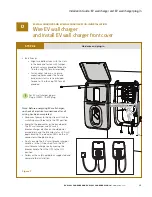
Page 16: ...ure 5 Figure 6 Hardwire Hardwire and plug in EV WALL CHARGER AND EV WALL CHARGER PLUG IN INSTALLATION Wire EV wall charger and install EV wall charger front cover D 1 2 3 4 Plug in two connectors located on the wire harness on the base to the circuit board on the cover Install two main neutral and ground wires Torque wire pressure screws to value shown on main label located inside of cover ...

Page 17: ... using T25 Torx bit provided For EV wall charger plug in Plug in NEMA 14 50P plug Note Before energizing EV wall charger re check all electrical connections after all wiring has been completed Reconnect power to the upstream circuit by switching circuit breaker to the ON position Energize the loadcenter or the panelboard The EV wall charger and EV smart breaker charger electronics should power imm...

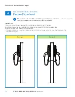
Page 18: ...40V rated two pole device Make sure to follow local code and NEC requirements Set aside hardware kit and mounting template included with the EV wall charger instructions mounting template won t be needed for installation EV WALL CHARGER PEDESTAL INSTALLATION Prepare EV pedestal A Single port Dual port This section describes installation of an EV charger directly onto an EV pedestal If you will be ...

Page 19: ...w eaton com Single port Dual port EV WALL CHARGER PEDESTAL INSTALLATION Prepare EV pedestal A Figure 8 STEP A 1 Remove the cover panels located on the rear of the unit starting with the cover panel in the middle of the unit 1 then removing the cover panel at the top 2 and lastly the bottom panel 3 1 1 2 2 3 3 2x ...

Page 20: ...e on the side s of the EV wall charger that is holding the cover to the base Remove the cover and set aside cautiously to avoid damage to the circuit board Remove largest knockout 1 diameter 1 375 inches from the EV wall charger base 2 for conduit fitting Remove center of knockout by driving it inward Remove subsequent rings using pliers by pulling the ring out around the edge of the ring To preve...

Page 21: ...r entry point on the front of the pedestal Note If you are not ready to install the EV charging station at this time do not remove the mechanical closer 1 Install the conduit fitting 2 through the EV pedestal upper 1 and EV wall charger base 3 Note The o ring 4 must be placed between the EV pedestal and the EV wall charger during installation Failure to do so will result in voiding any warranty 2 ...

Page 22: ...20 bolts 3 while installing washers and locknuts 4 and 5 Secure cord hook 6 to EV pedestal upper using two 1 4 20 bolts 7 Hold 1 4 20 bolts 7 while installing washers and locknuts 8 and 9 Single dual port EV WALL CHARGER PEDESTAL INSTALLATION Install EV wall charger base B 4 5 8 9 3 3 7 2 1 6 Reference 1 EV wall charger base 2 EV pedestal upper 3 1 4 20 x 0 625 inch machine screw x4 4 1 4 20 washe...

Page 23: ...V pedestal cutout 3 Plastic conduit fitting Figure 13 EV WALL CHARGER PEDESTAL INSTALLATION Run wiring through EV pedestal C 1 2 3 As illustrated route the conduit up through the base plate and center body of the EV pedestal 1 Pass the conduit through the cutout between the lower and upper EV pedestal sections 2 Route through the plastic conduit fitting 3 and into the EV wall charger ...

Page 24: ...V WALL CHARGER PEDESTAL INSTALLATION Replace cover plate s D For single port installation skip to Step H on page 28 Replace cover plates to the EV pedestal using the tamper resistant button head Torx screws 1 Reference 1 Stainless steel tamper resistant button headTorx screws 10 32 thread size 1 2 inch long x10 Figure 14 1 ...

Page 25: ... EV WALL CHARGER PEDESTAL INSTALLATION Replace cover plate D Install the top cover plate 1 using the tamper resistant button head Torx screws 2 Note Bracket studs 3 should be facing out Reference 1 Top section cover 2 Stainless steel tamper resistant button headTorx screws 10 32 thread size 1 2 inch long x10 3 1 4 20 studs x3 Figure 15 1 2 3 ...

Page 26: ...hrough the EV wall charger base and into top section cover Hold the bolt in place while installing a washer and locknut to the inside of the EV pedestal Reference 1 1 4 20 nylon locknut x4 2 1 4 20 washer x4 3 1 4 20 x 0 625 inch machine screw Figure 17 Replace the mechanical closer 1 Install the second EV wall charger base so that it properly aligns with the three 1 4 20 studs protruding through ...

Page 27: ...pedestal cutout 3 Plastic conduit fitting Figure 18 2 EV WALL CHARGER PEDESTAL INSTALLATION Run wiring through EV pedestal F 1 3 As illustrated route the conduit up through the base plate and center body of the EV pedestal 1 Pass the conduit through the cutout between the lower and upper EV pedestal sections 2 Route through the plastic conduit fitting 3 and into the EV wall charger ...

Page 28: ...lower access cover G STEP G 1 STEP G 2 Dual port Dual port Install cord hook first Install the access cover 1 to the EV pedestal upper section 2 using the tamper resistant button head Torx screws 3 1 3 2 Figure 19 Reference 2 Access cover 3 EV pedestal upper 4 Stainless steel tamper resistant button headTorx screws 10 32 thread size 1 2 inch long x8 Figure 20 ...

Page 29: ...ence 1 Access cover 2 EV pedestal lower 3 Stainless steel tamper resistant button headTorx screws 10 32 thread size 1 2 inch long x8 Figure 21 EV WALL CHARGER PEDESTAL INSTALLATION Install cord hook and lower access cover G 1 3 2 Install the lower access cover 1 to the EV pedestal lower section 2 using the tamper resistant button head Torx screws 3 ...

Page 30: ...er front cover H Install two main neutral and ground wires Torque wire pressure screws to value shown on main label located inside of cover Plug in two connectors located on the wire harness on the base to the circuit board on the cover STEP H 1 STEP H 2 Reference 1 BLACK Line 2 2 RED Line 1 3 WHITE Neutral 4 GREEN Ground Figure 22 Figure 23 Single dual port Single dual port L1 1 2 3 4 ...

Page 31: ...amper resistant screws provided Torque to 15 in lb using T25 Torx bit provided Note Before energizing EV wall charger re check all electrical connections after all wiring has been completed Reconnect power to the upstream circuit by switching circuit breaker to the ON position Energize the loadcenter or the panelboard The EV wall charger and EV smart breaker charger electronics should power immedi...

Page 32: ...1CBIMP003 RF radiation exposure statement This equipment complies with FCC RF radiation exposure limits set forth for an uncontrolled environment This equipment should be installed and operated with a minimum distance of 20 centimeters between the radiator and your body Canada low power license exempt radio communication devices RSS 210 Common information operation is subject to the following two ...

Page 33: ...t a Wi Fi signal is available where the EV smart breaker charger has been installed Get started by downloading the Green Motion EV Charger Manager app Available on IOS and Google Play stores Name your charger Enter your Wi Fi credentials Connect your breaker following the steps in the app To use the EV smart breaker charger with your preferred charge management system please visit our developer po...

Page 34: ...r maintenance not in conformance with Seller s recommendations including as set forth in these Terms and Conditions of Sale and industry standard practice or due to accident misuse abuse or negligence This warranty does not cover breach of data or system security including that of information technology infrastructure computers software hardware databases electronic systems including database mana...

Page 35: ... and solutions You can also refer to the installation video under the Resources section of the product web page Why is the charger s RED LED flashing after GFCI Test button is pushed The charger entered a permanent fault mode since a GFCI self test is initiated while the EV connector is not plugged into the EV Double press and hold the smart breaker display button for 15 seconds to clear the fault...

Page 36: ...ulevard Cleveland OH 44122 United States Eaton com 2022 Eaton All Rights Reserved Printed in USA Publication No IL191011EN August 2022 Eaton is a registered trademark All trademarks are property of their respective owners ...

Reviews: