


4
EATON
ET4001 Crimp machine operator´s manual W-EQCR-TM022-E3 March 2019
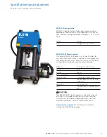
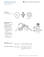
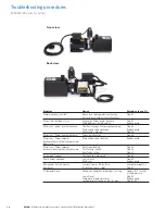
Figure 3
ET4001P-002 Outlet port
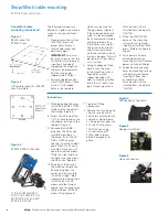
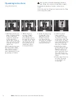
Shop/Work table mounting
ET4001 Press and pump
The following methods are
offered as a guide and may be
varied to suit your particular
needs.
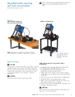
1. Prepare mounting surface
for ET4001 press and
pump. Refer (Figure 1)
for bolt hole layout and
optimum height.
IMPORTANT:
Care must
be taken to insure that the
surface to which the press
is bolted is capable of
supporting the weight of
the press (approximately
500 lbs.) and pump
(approximately 75 lbs).
2. Remove shipping carton
from ET4001 press. There
are four
5
/
8
-18 tapped
holes in the top plate
which may be used for
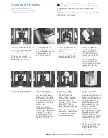
lifting purposes (Figure 2).
If these tapped holes are
used, it is recommended
that a minimum of two be
utilized, preferably four.
If two holes are used for
lifting, use holes directly
across from each other
on the center line and not
two on a diagonal. This will
prevent press from tilting
as it is raised.
3. Using an adequate lifting
device, raise the press
to the mounting surface.
Align holes in press
support brackets with
holes in mounting surface.
Insert four ½” bolts from
top of mounting surface.
Washers and nuts are
installed from underneath.
TIGHTEN.
4. Place the ET4001P-002
pump on the mounting
surface to the right and
slightly behind the ET4001
press. (Reference figure 8,
Page 5)
5. Mark power unit base
plate hole pattern on
mounting surface. Remove
power unit and drill holes.
6. Replace pump and align
holes on mounting surface
with base plate of pump.
Insert bolts from top
of mounting surface.
Washers and nuts are
installed from underneath.
TIGHTEN.
Figure 1
Bench layout for
ET4001 press
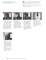
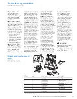
Figure 4
Connection at top plate
Figure 5
Gauge installation
Figure 6
Hose connection
Figure 2
Lifting hole layout on ET4001
press top plate
Shop/Work table
mounting instructions*
IT IS RECOMMENDED
THAT THE PUMP BE ON
AN INDIVIDUAL 20 AMP
SERVICE OUTLET.
7. Standing behind the press,
install the # 8ORB x ORFS
fitting into the top port of
the crimper (Figure 4).
8. Screw the 90º end of the
T-410-22 hose loosely onto
the adapter installed in the
top port (Figure 4).
9. Remove the 08ORB
plug from the D05 valve
manifold mounted on
the pump. Install the 90º
ORB x ORFS adapter.
Loosely install the straight
end of the T-410-22 hose
assembly. Note, you will
need to orient the elbow
fitting in a slight angle so
the hose assembly clears
the D05 valve (Figure 6).
10. Standing at the back of
the machine, remove the
#4 pipe plug from the
center of valve manifold.
Install the straight pipe
nipple into the pump. Then
install the #4 size, 90º
elbow onto the straight
adapter and the gauge into
the female port of the 90º
elbow fitting (Figure 5).
11. Tighten all fitting
connections.
12. Remove the tank plug and
screw in reservoir vent
cap. Screw black cord into
switch on shroud (Figure
3). Plug electrical plug into
220 volt 20 amp circuit.
*NOTE: When using
Cart (part number FF
91042) holes are pre-
drilled. See page 5 for
photo.
Instructions


