ELC Distributed I/O Adapters
For More Information visit:
www.eaton.com
MN05002003E
132
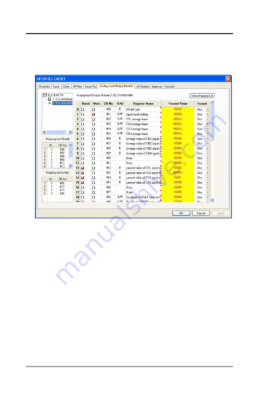
Click Apply and the chosen values will be added to the Read and Write Mapping tables on the
left side of the screen. Note that 8 input words are mapped along with 4 output words, per the
screen below. Note exactly how this data is mapped, it will be needed later when writing the
PLC program.
Click OK to save the configuration and exit this screen.
The ELC-CAENET module creates an Input Image with all possible discrete inputs (256 bits or
16 words) followed by the analog input data. It also creates an Output Image with all possible
discrete outputs (256 bits or 16 words) followed by the analog output data. The I/O data in the
CAENET module will be as follows:
Input Image:
Discrete Input words 0-15: all possible discrete inputs
4 Analog Input Words for each analog module: total 8 input words
Total input words = 24 words.
Output Image:
Discrete Output words 0-15: all possible discrete outputs
3 Analog output words for the AN06 module and 1 analog output word for the AN04 module
Total output words: 20 words.


