


9
Mounting and Operating Instructions DualGuard-S ESF30 KV
40071860406 (A) March 2022 www.eaton.com
6 Assembly and installation DualGuard-S ESF30 SOU5, SOU4, SOU3, SOU2, SOU1
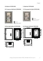
4 x fasteners
1 x double bit key
1 x instruction manual
1 x maintenance checklist (
2. Lift the system with a suitable lifting device e.g. scissor
lift truck to the specified installation height.
3. Align the manifold vertically on the wall and secure it
with the the pre-drilled holes in the back panel/fixing lug.
Observe the diagonal dimension. Do not drill into the rear
wall! Caution: Danger of breakage!
4. Component thickness
6 Assembly and installation
DualGuard-S ESF30 SOU5, SOU4, SOU3,
SOU2, SOU1
6.1 Wall mounting
General notes
Uneven wall surfaces that are not touched by the fire pro-
tection system, are to be (Crystal-CEL), provided that these
have a gap of more than 5 mm or if smoke is likely to escape
in the event of a fire. Walls must be level and plumb.
Normal tolerances of the walls/plaster must be compensated
for in such a way that smoke- and fire-proof installation is
possible.
For the installation on the wall, only the materials described
in the the „General Building Inspectorate Approval“ may be
used. The wall on which the distributor is to be mounted
must have sufficient load-bearing capacity. The fire resi-
stance of the supporting walls should be at least as high as
that of the distributor. With the help of the enclosed screw
anchors, DualGuard-S ESF30 can be easily screwed on via
the fastening holes in the housing - in both cracked and
non-cracked concrete. A distance of at least one metre from
neighbouring installations such as gas or water is required.
In In the vicinity of doors, a distance corresponding to the
door must be maintained.
1. Check the accessories for completeness:
6.2 Inserting the cables
The cable entry as a system component of the electrical
enclosure consists of:
a) a metal cover,
b) the intumescent and
endothermic areas The metal cover with different dimensi-
ons, depending on the type of distribution board, is provided
with holes. The cables are to be inserted through these holes.
To do this, the insulation layer visible through the holes must
be removed with a drill (with a drill bit approx. 2 mm smaller
than the diameter of the cable). This makes it easier to insert
the cable. When piercing the red or blue intumescent, make
sure that the the red or blue intumescent must be guided
straight. To achieve strain relief for the cables, a cable rail is
to be mounted on the equipment support inside the cabinet
and directly in front of the cable inlet outside the cabinet and
attach the cables to it.
The exact drilling depth depends on the dowel length and
is to be be determined as follows: Required drilling depth
= anchor length
- component thi 10 mm
- Minimum anchoring depth of the enclosed dowels: 70 mm;
- Drill diameter: 10 mm
5. Suck out the drill dust, drive in the dowel - through-fixing
(screw head flush) and tighten the screw screw with a
suitable wrench/screwdriver - do not overtighten! tighten
- do not overtighten! Do not countersink the screw head
into the into the material.
6. Push the plastic caps onto the fastening anchors and press
them firmly. and press firmly. (optional)
7. Spray the plastic caps of the fastening anchors with fire
protection putty to around the plastic caps of the fastening
anchors to ensure the protection class. (optional)


