3 Installation
3.6 Electrical Installation
DC1-S…20…, DC1-S…OE1 Variable Frequency Drives
05/21 MN040058EN
www.eaton.com
83
3.6.3 Thermistor connection
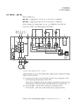
Motor thermistors and motor thermal switches (Thermoclick) can be
connected to control signal terminal 4 (DI3 = digital input 3) in order to
provide protection against thermal motor overloads.
In this case, parameter P-15 must be used to select the EXTFLT
(external fault) setting for DI3, and parameter P-47 must be set to a value of
6 (
Ptc-th
).
Figure 56: Thermistor connection
The thermistors and thermal switches used must be PTC-type units (PTC
characteristic, positive temperature coefficient).
The tripping range must fall within a resistance value range of approximately
2.5 - 3 k
Ω
, while the reset range must fall within a range of 1.9 - 1 k
Ω
.
T1
T2
M 3 ∼
Thermoclick sensor
ϑ
ϑ
U
V
W
PE
PTC type
≧ 2.5 kΩ trip level
≦ 1.9 kΩ Reset
PES
1 2 3 4 5 6 7 8 9 10 11
Summary of Contents for DC1-S1011NB-A20CE1 1
Page 4: ......


