I.B. ATS-CP01
Effective 5/98
Cutler-Hammer
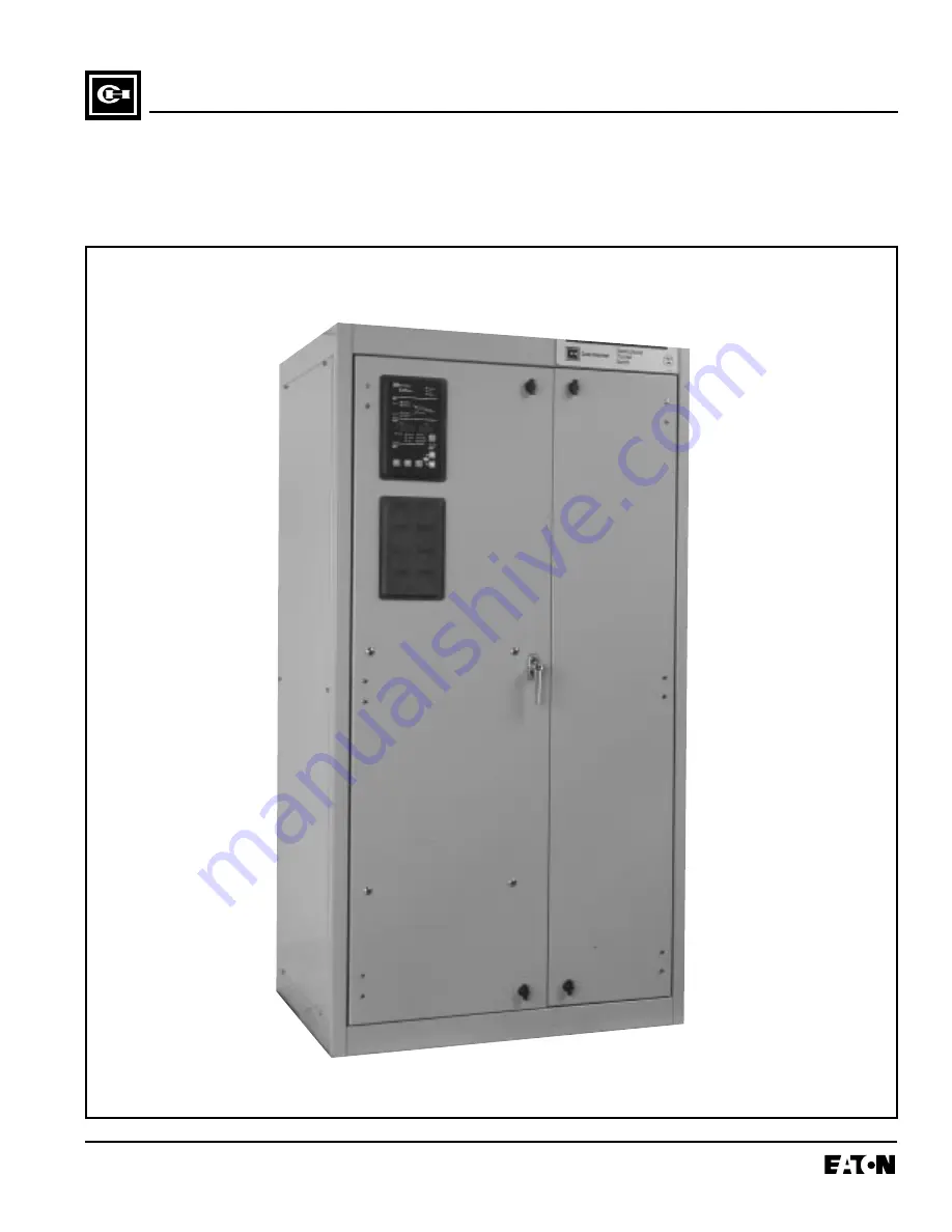
Instructions for Cutler-Hammer Closed Transition Fixed Mount SPB Transfer Switch
Page 1: ...I B ATS CP01 Effective 5 98 Cutler Hammer Instructions for Cutler Hammer Closed Transition Fixed Mount SPB Transfer Switch ...
Page 2: ......
Page 3: ... THAT CAN CAUSE DEATH OR SEVERE PERSONAL INJURY FOLLOW PROPER INSTALLATION OPERATION AND MAINTENANCE PROCEDURES TO AVOID THESE VOLTAGES WARNING TRANSFER SWITCH EQUIPMENT COVERED BY THIS INSTRUCTION BOOK IS DESIGNED AND TEST ED TO OPERATE WITHIN ITS NAMEPLATE RAT INGS OPERATION OUTSIDE OF THESE RATINGS MAY CAUSE THE EQUIPMENT TO FAIL RESULTING IN DEATH SERIOUS BODILY INJURY AND OR PROPERTY DAMAGE A...
Page 4: ...ng 5 2 2 Handling 5 2 3 Storage 5 SECTION 3 EQUIPMENT DESCRIPTION 3 1 General 6 3 2 Power Panel 6 3 2 1 Main Contacts 6 3 2 2 Load 7 3 2 3 Transfer Mechanism 7 3 3 Voltage Selection Panel 8 3 4 Logic Panel 8 3 5 Neutrals 8 3 6 Options Non Logic Panel 8 3 7 Enclosure 10 3 8 Standards 11 SECTION 4 INSTALLATION AND WIRING 4 1 General 12 4 2 Mounting Location 12 4 3 Mounting Procedure 12 4 4 Power Cab...
Page 5: ...g 20 6 2 1 Transfer Switch Appears Inoperative 21 6 2 2 Transfer Switch will not Automatically Transfer to Normal 21 6 2 3 Transfer Switch will not Automatically Transfer to Emergency 21 6 2 4 Transfer Switch will not Automatically Recharge Switches 21 SECTION 7 MAINTENANCE 7 1 Introduction 22 7 2 Procedures 22 ...
Page 6: ...3 8 Charger Mounting Dimensions in Inches mm 10 3 9 Typical Mini Switch Enclosure 10 4 1 Enclosed Fixed Mount Transfer Switch 600 4000 amperes 13 4 2 Enclosed Fixed Mount Transfer Switch 600 1200 ampere without Option 17C 14 4 3 Side View and Rear View of Power Panel terminal connections for SPB 800 1200 AMP 16 4 4 Seismic Tested and Approved Product Mounting Instructions 17 5 1 Pumping Handle Cha...
Page 7: ...NCLUDED AS PART OF THE PROCEDURAL STEPS IN THIS DOCU MENT ARE FOR PERSONNEL SAFETY AND PRO TECTION OF EQUIPMENT FROM DAMAGE AN EXAMPLE OF A TYPICAL WARNING LABEL HEAD ING IS SHOWN ABOVE TO FAMILIARIZE PERSON NEL WITH THE STYLE OF PRESENTATION THIS WILL HELP TO INSURE THAT PERSONNEL ARE ALERT TO WARNINGS WHICH APPEAR THROUGH OUT THE DOCUMENT IN ADDITION CAUTIONS ARE ALL UPPER CASE AND BOLDFACE COMP...
Page 8: ...nd the transfer mechanism to effect the transfer of the main contacts from source to source Transfer of power however is accomplished by true hand opera tion not power assisted of the transfer switch This switch is similar to the basic switch in that an intelli gence circuit and a motor driven mechanism are not part of the design Non Automatic Transfer Switch Electrically Operated This transfer sw...
Page 9: ...0V Maximum Fuse 600V max Amp Rating Selected kA kA kA Fuse Rating Type kA 600 No 85 65 25 800 1200 L 200 800 No 85 65 25 1200 1600 L 200 1000 No 85 65 25 1600 L 200 1200 No 85 65 25 2000 L 200 600 Yes 100 100 85 800 1200 L 200 800 Yes 100 100 85 1200 1600 L 200 1000 Yes 100 100 85 1600 L 200 1200 Yes 100 100 85 2000 L 200 1600 100 100 85 3000 L 200 2000 100 100 85 3000 L 200 2500 100 100 85 4000 L...
Page 10: ...ansfer Switch Catalog Number Explanation The switching devices have a high withstand rating Table 1 1 The high speed stored energy switch ing mechanism guarantees a transfer time of less than 5 cycles 1 3 TRANSFER SWITCH CATALOG NUMBER IDENTIFICATION Transfer switch equipment catalog numbers provide a significant amount of relevant information that pertains to a particular piece of equipment The c...
Page 11: ... not discard the packing material until the equipment is ready for installation A plastic bag of documents will be found within the enclosure usually attached to the inside of the door Important documents such as test reports wiring dia grams appropriate instruction leaflets and a warranty registration card are enclosed within the bag and should be filed in a safe place 2 2 HANDLING As previously ...
Page 12: ... in accordance with the specific requirements of the circuit being controlled Each transfer switch is therefore tailor made to a specific application 3 2 POWER PANEL The power panel consists of a means for making load power and neutral connections The main contacts and the transfer mechanism are all on one steel frame Figures 3 1 3 2 1 MAIN CONTACTS The main contacts connect and disconnect the loa...
Page 13: ...ated case switches with a stored energy mechanism An electrical operator automatically recharges the mechanism after the switch ing device has been closed An indicator on the switch shows whether it is in the OPEN or CLOSED position and the status of the stored energy mechanism Figure 3 2 Figure 3 3 Insulated Case Circuit Breaker Figure 3 4 Side View and Rear View of Power Panel terminal connectio...
Page 14: ...3 6 Detailed information is presented in a separate document IQ Transfer Instruction Book 3 5 NEUTRALS All 2 pole and 3 pole transfer switches are equipped with 100 percent rated neutral connections Figure 3 7 Different lug configurations are available Option 21A 3 6 OPTIONS NON LOGIC PANEL Switch options which are not part of the logic scheme are available to meet a variety of other application r...
Page 15: ...space and requires less wiring B Both Normal and Emergency Sides E Emergency side only N Normal side only 17C High Withstand Rating Increases withstand rating from 65 kA to 100 kA at 480 volts 18 IQ Metering I IQ Generator Normal Only J IQ Generator Emergency Only K IQ Generator Both N E Selectable O IQ Analyzer Normal Only P IQ Analyzer Emergency Only Q IQ Analyzer Both N E Selectable R DP 4000 N...
Page 16: ...onnec tion with external pilot light for disconnect indication also includes Option 16 B Same as A except includes ground fault protection 41 Space Heater with Thermostat A 100 Watts B 200 Watts C 400 Watts 42 Seismic Withstand Capability Provides transfer switch with seismic capability exceeding the worst case Zone 4 required levels per both the Uni form Building Code and the California Building ...
Page 17: ...ational Electrical Code and or c In legally required stand by systems in accordance with article 701 of the National Electrical Code Cutler Hammer Automatic Transfer Switches are avail able to meet NFPA 110 for emergency and stand by power systems and NFPA 99 for health care facilities when ordered with the appropriate options Since Cutler Hammer Automatic Transfer Switches uti lize specially desi...
Page 18: ...d to retard the action of relays or cover the logic in a way that restricts adjustments Maintain proper electrical clearances between live metal parts and grounded metal For installation and maintenance purposes the primary and secondary sources must have an overcurrent pro tective device upstream of the transfer switch unless overcurrent protection is integral to the switch Dimensions of the tran...
Page 19: ... Connections Neutral Cable Connection Grounding Right hand side when facing front switch F I G H F I G H Transfer Dimensions Conduit Opening Wt Switch A B C D Rating in cm in cm in cm in cm lb kg 3 Pole Fixed 28 00 71 1 50 00 127 0 23 50 59 7 22 00 55 9 1300 590 800 1200 4 Pole Fixed 34 00 86 4 50 00 127 0 29 50 74 9 22 00 55 9 1400 635 800 1200 3 Pole Fixed 48 00 121 9 60 00 152 4 43 25 109 9 22 ...
Page 20: ... Normal Power Cable Connections Neutral Cable Connection Grounding Load Cable Connections Emergency Power Cable Connections Front View Side View Side View with Panel Removed Top View Transfer Wt Switch Rating lbs kg 3 pole 600 1200 A 850 386 4 pole 600 1200 A 950 431 Dimensions are in inches centimeters AUTOMATIC NON AUTOMATIC AND MANUAL TRANSFER SWITCHES Enclosures meet all current applicable NEM...
Page 21: ... plate on the intelli gence panel of transfer switch agree with sys tem current and voltage Step 3 After the transfer switch is mounted provide conduit or cable openings as required Ensure that no metal filings contaminate the transfer switch components Step 4 Test all power cables before connecting to the unit to insure that conductors or cable insulation have not been damaged while being pulled ...
Page 22: ...G TO PERFORM ANY WIRING ACTIVITY TO OR WITHIN THE TRANS FER SWITCH EQUIPMENT Power sources load conductors and control wiring should be connected to locations as indicated in the Customer Wiring Diagrams supplied with the transfer switch equipment 4 6 1 ENGINE START CONNECTION The engine control contact connections are located on the lower right of the transformer panel of the ATS Figure 3 5 Conne...
Page 23: ... remote alarming These contacts are energized when the TDUP Time Delay Utility Parallel times out preset by user The TDUP timer starts timing when both sources are paralleled Refer to the IQ Transfer instruction book for additional alarms These cleats must be ATVISP NTVSSP Figure 4 4 Seismic Tested and Approved Product Mounting Instructions CTVISP ...
Page 24: ...fea tures and selected options Operation of an automatic transfer switch during normal power source failure nor mal power source restoration and performing tests will be described here with only standard options included on the switch Additional options as described in Section 3 or in separate instruction documents can change sequences and timing depending upon the options selected Become familiar...
Page 25: ...CONTACTS Alternate and Normal Sources must be Synchronized 7805C60H02 THIS PRODUCT CONTAINS A SPECIAL CON TACT ARRANGEMENT OVERLAPPING CON TACTS MISUSE CAN RESULT IN DEATH SEVERE PERSONAL INJURY OR PROPERTY DAMAGE THIS LABEL IS APPLIED TO THE DEAD FRONT COVER Do Not Use Without Reading Manual Operating Instructions MANUAL CLOSE BUTTON FOLLOW THE INSTRUCTIONS OUTLINED IN THE NEXT WARNING LABEL THIS...
Page 26: ...CT WITH ANY VOLTAGE SOURCE WHILE PROBLEM SOLV ING ONLY PROPERLY TRAINED PERSONNEL FAMILIAR WITH THE TRANSFER SWITCH EQUIPMENT AND ITS ASSOCIATED EQUIPMENT SHOULD BE PERMIT TED TO PERFORM THE PROBLEM SOLVING FUNC TION IF AN INDIVIDUAL DOES NOT FEEL QUALI FIED TO PERFORM THE PROBLEM SOLVING FUNC TION THE INDIVIDUAL SHOULD NOT ATTEMPT TO PERFORM ANY OF THESE PROCEDURES A basic problem solving effort ...
Page 27: ...t trip in emergency switch If NO Check wiring to A9 and A8 Step 5 Measure voltage between terminals A1 and A2 on the normal switching device spring release coil Does the voltage measure 120 VAC 10 volts Record reading If YES Check spring release coil in normal switching device If NO Check wiring to A1 and A2 6 2 3 TRANSFER SWITCH WILL NOT AUTOMATI CALLY TRANSFER TO EMERGENCY Step 1 Check for prope...
Page 28: ...f application conditions and the importance placed on dependable operation by this type of equipment inspection and maintenance checks should be made on a regularly scheduled basis Since equipment maintenance will consist mainly of keeping the equipment clean the frequency of mainte nance will depend to a large extent on the cleanliness of the surroundings If a significant amount of dust or foreig...
Page 29: ...ty c Inspect switching devices for dust dirt soot Remove dust dirt soot grease moisture and corrosion grease moisture or corrosion contamination from the surface of the switching device using a dry soft lint free cloth dry soft bristle brush and vacuum cleaner Do not blow debris into circuit breaker or nearby breaker structure If contamination is found look for the source and fix the problem d Che...
Page 30: ...I B ATS CP01 Page 24 Effective 5 98 ...
Page 31: ......
Page 32: ...tract between the purchaser and Cutler Hammer NO WARRANTIES EXPRESSED OR IMPLIED INCLUDING WARRANTIES OF FITNESS FOR A PAR TICULAR PURPOSE OR MERCHANTABILITY OR WARRANTIES ARISING FROM COURSE OF DEAL ING OR USAGE OF TRADE ARE MADE REGARDING THE INFORMATION RECOMMENDATIONS AND DESCRIPTIONS CONTAINED HEREIN In no event will Cutler Hammer be responsible to the purchaser or user in contract in tort in...