IF 1897 • 10/19 Copyright © 2019, Eaton’s Crouse-Hinds Division Page 2
INSTALLATION
A. ZP1057MTK Back/Ceiling Mount
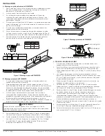
1. For back mount, use the bracket as a template, mark and drill holes into
the mounting surface and use supplied 5/16” bolts (see Figure 2).
2. Luminaire is now ready for mounting.
3. It is strongly suggested to use two (2) qualified tradespeople to proceed
with the final mounting of the luminaire. This is recommended to avoid
any personal injury or damage to the luminaire.
4. Place the four (4) 5/16” bolts through the mounting plate and tighten
evenly to the support structure. Minimum torque 138 in.-lbs. (15.6 N-m).
5. Make sure the power is disconnected from the conduit system before
installing the luminaire.
6. Slide the luminaire into the mount bracket, engaging the flange on the top
of the luminaire and position it near the center. For final positioning, adjust
to dimension B in the table below.
7. Tighten the four (4) 1/4” set screws on the slide bracket until they bottom.
Torque to 78 in.-lbs. (8.8 N-m).
Length
(in)
(mm)
A
44.6
1133
B
16.3
414
A
B
283
11.14
50.8
2.00
144.4
5.69
165.1
6.50
12.7
.50
MAX
A
1/4" Set Screws
B
304.8
12.00
50.8
2.00
112.3
4.42
Figure 2. ZP1057MTK Back Mount Installation
B. ZP1050MTK Swivel Mount
1. Make sure the power is disconnected from the conduit system before
installing the luminaire.
2. Mark and drill holes for fastening swivel brackets. Use two (2) 3/8” bolts
(not supplied) at center to center measurements. For swivel brackets,
holes may be spaced as required. It is required to keep them at least 18”
(457mm) apart (see Figure 3) (see table for full mounting range).
3. Luminaire is now ready for mounting. It is strongly suggested to use
two (2) qualified tradespeople to proceed with the final mounting of the
luminaire. This is recommended to avoid any personal injury or damage to
the luminaire.
4. Slide the luminaire into the mount brackets, engaging the flange on the
top of the luminaire and position it near the center.
5. Tighten the two (2) 1/4” set screws on each slide bracket until they
bottom (see Figure 4). Torque to 78 in.-lbs. (8.8 N-m).
6. Adjust the position of the luminaire to the desired angle and tighten the
two (2) 5/16” pivot bolts. Torque to 138 in.-lbs. (15.6 N-m).
7. Tighten the two (2) 1/4” pivot locking nuts at the adjustment slots to 78
in.-lbs. (8.8 N-m).
WARNING
Do not let the luminaire hang or flex on one bracket at a time. Failing to
comply will result in breakage of bracket and possible injury or death.
!
Length
(in)
(mm)
A
44.6
1133
B
18-47
222-1194
Figure 3. ZP1050MTK Swivel Mount Installation
Pivot Bolt
Pivot Locking Nut
Slide Bracket
1/4” Set Screws
Figure 4. Swivel Mount Detail
C. PM KIT – POLE MOUNT
1. Make sure the power is disconnected from the conduit system before
installing the luminaire.
2. Verify that the clamp (see Figure 6) internal diameter is consistent with
the diameter of the pole prior to installation. Clamps are available in 1.65”
(42mm), 2.00” (51mm) and 2.36” (60mm) sizes.
3. Pole mount brackets may be spaced as required; it is required to keep
them at least 18” (457mm) apart (see Figure 5) (see table for full
mounting range).
4. Slide the two (2) pole mount brackets onto the luminaire, engaging the
flange on the top of the luminaire.
5. Tighten the two (2) 1/4” set screws on each slide bracket until they
bottom (see Figure 6). Torque to 78 in.-lbs. (8.8 N-m).
6. Remove the two (2) 5/16” screws, lock washers and nuts on each clamp
and remove the upper clamp halves.
7. Luminaire is now ready for mounting. It is strongly suggested to use
two (2) qualified tradespeople to proceed with the final mounting of the
luminaire. This is recommended to avoid any personal injury or damage to
the luminaire.
8. Lift luminaire into position such that the pole fits into the lower clamp
halves.
9. Install the two (2) upper clamp halves and the 5/16” screws, lock washers
and nuts on each clamp.
10. Tighten the nuts on the 5/16” screws evenly using a back and forth
sequence. Torque to 138 in.-lbs. (15.6 N-m).
A
B
2X
11.1
Ø .437
165.1
6.50
73
2.88
190.1
7.49
A
B
2X
14.6
.58


