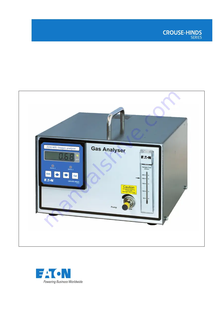
Z230
MTL zirconia oxygen analyser
February 2017INM 130-0186 Rev 8
Instruction manual
MTL gas analysers & systems
Page 1: ...Z230 MTL zirconia oxygen analyser February 2017 INM 130 0186 Rev 8 Instruction manual MTL gas analysers systems ...
Page 2: ...CLARATION OF CONFORMITY A printed version of the Declaration of Conformity has been provided separately within the original shipment of goods However you can find a copy of the latest version at http www mtl inst com certificates ...
Page 3: ...ions 3 3 INSTALLATION 4 3 1 Unpacking and visual checking 4 3 2 Calibration overview 4 3 3 Sample 4 3 3 1 Key requirements 4 3 3 2 General advice Sample 5 3 3 3 Measuring low levels of oxygen 5 3 4 Electrical connections 6 3 4 1 Measuring low levels of oxygen 6 3 4 2 RS232 Connection 4 3 4 3 Alarm and Analogue Output connections 6 4 COMMISIONING 7 4 1 Switching on 7 4 2 Programming 7 4 2 1 Analogu...
Page 4: ...iv INM MTL 130 0186 Rev 8 THIS PAGE IS LEFT INTENTIONALLY BLANK ...
Page 5: ... labelling Normal relates to process normal and not the electrical rest position of the relays In process normal the relays are energised 1 2 Manual symbols The following methods are used in this manual to alert the user to important information WARNING Warnings are provided to ensure operator safety and MUST be followed WARNING This symbol alerts you to the presence of hazardous voltages Refer to...
Page 6: ...n 2 7 Speed of response T 90 less than 4 seconds at 300ml min sample flow 2 8 Sample inlet pressure no pump fitted 10mbar to 8bar 2 9 Sample temperature 100 C maximum at the analyser 2 10 Sampling system material Dependent upon sampling system Stainless steel platinum zirconia nickel brass aluminium alumina PTFE nitrile rubber and nylon 2 11 Sample connections Dependant upon sampling system Nickel...
Page 7: ... Volt free C O contacts rated at 48v 0 5A AC or DC normally energised 2 14 Serial Communication Port RS232 DCE 9w female D connector 2 15 Environment Operating 0 C to 45 C RH 15 to 90 non condensing Storage 20 C to 55 C RH 15 to 90 non condensing 2 16 Power supply 100 260V AC 50 60 Hz unit Maximum power consumption 30VA 2 17 Dimensions 255mm w x 170mm h x 260mm d ...
Page 8: ...d be kept to a minimum Ambient air must contain a normal Oxygen level WARNING The case should not be exposed to water jets or drips Figure 1 Instrument dimensions 19 rack mounting 3U high 3 3 Sample WARNING It is important that no flammable mixtures are allowed to come into contact with the measuring cell as this may cause ignition of the gas Gases containing halogens sulphur or silicon must be av...
Page 9: ... the risk of pressuring the cell Most analysers are supplied with a built in sample flow regulating valve If a valve is fitted in the sample outlet pipe work it is important to remember that it must be the last to be shut 3 3 3 Measuring low levels of oxygen All piping should be of good quality material with sound joints and couplings When measuring concentrations of less than 500ppm oxygen very s...
Page 10: ... 2 2 3 TX Data transmitted from instrument 3 3 2 3 4 3 Alarm and Analogue Output connections See figure 2 CAUTION The recommended cable used for external connection is double insulated WARNING Although relay contacts are rated at 48V AC or DC voltages above 33V AC are defined as hazardous by BSEN61010 1 Safety requirements for electrical equipment for measurement control and laboratory use Appropr...
Page 11: ... through a sequence of adjustable parameters The sequence is as follows Analogue Output top scale value Analogue Output low scale value Alarm 1 Set point Alarm 1 Hysteresis Alarm 1 Mode Alarm 2 Set point Alarm 2 Hysteresis Alarm 2 Mode wraps All Programming screens operate on the same principle use the or arrows to scroll through the parameters By pressing Edit and the x in the xP nnnn will flash ...
Page 12: ... 1 The value is in of the set point or alarm level and is variable from zero to 10 5P xxxx The display shows 5P x where x indicates the operating mode of the alarm as follows 0 Alarm off H High alarm when above set point L Low alarm when below set point S Status alarm while cell heater is warming up 4 2 3 Alarm 2 The operation of alarm 2 is identical to that of alarm 1 The menu entries are as foll...
Page 13: ...0 3P 100 2P 0 00 1P 20 9 HE 20 9 P 0 29 Alarm 1 mode 0 Off H High alarm L Low Alarm Alarm 2 mode 0 Off H High alarm L Low Alarm Offset Slope High Calibration Accept edit Cal Warming up Alarm 2 Hysteresis Alarm 2 setpoint Alarm 1 Hysteresis Alarm 1 setpoint 4mA set point 20mA set point Low Calibration Software version Software number Normal measurement mode At switch on To Edit a Parameter Flashing...
Page 14: ...e oxygen concentration as the normal sample As with most instruments of this type it is important to have a reasonable concentration difference between the two calibration points For the Z230 the recommended difference is 0 25 decades i e LOG H concentration L concentration 0 25 Because the most common high level gas is air in order to maintain an adequate difference in concentration the instrumen...
Page 15: ... press the Edit button to store the calibration setting or Cal to cancel To return the unit to measuring mode press and release the Cal button otherwise the or arrows until the displaychanges to L xxxx to continue with setting the Low calibration point 5 3 2 Low point calibration Change the sample gas supply to the Low level concentration and establish a flow of the gas through the analyser In mea...
Page 16: ...to be adequate WARNING Opening the analyser case will expose you to mains voltage Disconnect the analyser from the mains supply and any potentially hazardous process wiring before opening the case 6 1 Ordering parts Should a failure occur return the instrument to your local MTL Gas sales office for repair When ordering spares or raising queries on the instrument it is important to quote its serial...
Page 17: ...ed by the Nernst equation Cell output 2 303RT log P1 4F P2 where R molar gas constant T absolute temperature of cell in K F Faraday constant P1 partial pressure of oxygen in the reference air in most cases P2 partial pressure of oxygen in the sample Thus with air on both sides of the cell the output is zero log1 0 The reference electrode is negative with respect to the sample electrode for sample ...
Page 18: ...sage terminator CR LF 9 A response message maximum duration is defined as 3 second This is the maximum time from the first valid response character to the last message terminator CR LF This is to allow multiple line responses No card response can hold the bus for more than 3 seconds Factory commands are the only exception 10 exceptions to 7 8 9 Starting up The card start up is defined as taking up...
Page 19: ...ns 3 N A D3 0 N A D2 Sens 2 11 56mV D2 11 56 Thermocouple mV D1 Sens 1 11 55mV D1 11 55 Oxygen cell mV AxEy Error logs read only except E9 E9 Clear Log 0 E9 0 1 to clear logs Clear all counters E8 Calibration 0 E8 0 Calibration error counter E7 Sensor 0 E7 0 Sensors error counter E6 AO 0 E6 0 Analogue output counter E5 Float 0 E5 0 Float error counter E4 CRC 0 E4 0 EEPROM CRC error counter E3 Othe...
Page 20: ...ndition 110 of instrument span xxxxx will be e g R1 Conc Similarly in under range condition 5 of instrument span xxxxx will be In the case of a system error R1 will be replaced by the error code e g 72 In verbose mode a brief fault description will be appended Conc are determined by sensor type and unit see U below Resolution is applica tion dependant Where a fault is present in the secondary read...
Page 21: ...llegal for this board 71 79 CRC error NVRAM errors Error 71 user parameters CRC error if this area is restored user calibration etc is LOST Error 71 will be reported in response to ANY read request until either a calibration is performed or the instrument rebooted Error 73 75 automatically clear themselves so will not be seen Errors 72 74 76 will be reported in response to any read request and can...
Page 22: ...18 INM MTL 130 0186 Rev 8 THIS PAGE IS LEFT INTENTIONALLY BLANK ...
Page 23: ...INM MTL 130 0186 Rev 8 19 THIS PAGE IS LEFT INTENTIONALLY BLANK ...
Page 24: ...trozavodskaya Str 33 Building 4 Moscow 107076 Russia Tel 7 495 981 3770 Fax 7 495 981 3771 E mail mtlrussia eaton com SINGAPORE Cooper Crouse Hinds Pte Ltd No 2 Serangoon North Avenue 5 06 01 Fu Yu Building Singapore 554911 Tel 65 6645 9864 6645 9865 Fax 65 6 645 9865 E mail sales mtlsing eaton com SOUTH KOREA Cooper Crouse Hinds Korea 7F Parkland Building 237 11 Nonhyun dong Gangnam gu Seoul 135 ...