background image

10

Montage- und Betriebsanleitung GuideLed 10011 DX/DXC CG-S    40071860286(C)    Juli 2017     www.ceag.de

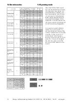
5.4 Betriebsmodus

5.4 Operating mode

Status / 

Order ZB-S

Schaltkontakt / 

Switch contact

Piktogramm / 

Pictogram

Rotes Kreuz / 

Red X

Open

0%

0%

Closed

10%

100%

Open

100%

0%

Closed

10%

100%

Open

100%

0%

Closed

10%

100%

Open

0%

0%

Closed

33%

100%

Open

100%

0%

Closed

33%

100%

Open

100%

0%

Closed

33%

100%

Open

0%

0%

Closed

10%

Blinking

Open

100%

0%

Closed

10%

Blinking

Open

100%

0%

Closed

10%

Blinking

Open

0%

0%

Closed

10%

Intervall

Open

100%

0%

Closed

10%

Intervall

Open

100%

0%

Closed

10%

Intervall

Open

100%

0%

Closed

10%

100%

Open

Intervall (10%/100%)

0%

Closed

10%

100%

Open

100%

0%

Closed

10%

100%

Open

100%

0%

Closed

10%

100%

Open

Intervall (10%/100%)

0%

Closed

10%

100%

Open

Intervall (10%/100%)

0%

Closed

10%

100%

Open

33%

100%

Closed

0%

0%

Open

33%

100%

Closed

100%

0%

Open

33%

100%

Closed

100%

0%

OFF

Bereitschaftslicht 

Non-

maintained 

mode

Intervall

Dauerlicht

Maintained 

mode

Geschaltetes 

Dauerlicht (über S3 

S4/DLS3PH) 

Switched 

maintained 

mode (via S3 

S4/DLS3PH) 

Blinking

rotes Kreuz im 
Normalbetrieb

Red cross in normal 
mode

H

OFF

ON 

Emergency 

ON

Erhöhte Sichtbarkeit 
in AC/DC B 
rotes Kreuz

Increased Affordance 
mode AC/DC + Red 
cross

F

OFF

ON 

Emergency 

ON

Erhöhte Sichtbarkeit 
in AC B rotes 
Kreuz

Increased Affordance 
mode AC + Red 
cross

E

OFF

ON 

Emergency 

ON

Emergency 

ON

ON 

OFF

D

Rotes Kreuz Intervall

Red Cross Intervals

ON 

Emergency ON 

Notlicht Ein 

Emergency 

ON

C

OFF

ON 

Emergency 

ON

Rotes Kreuz blinkend

Red Cross blinking

B

OFF

ON 

Emergency 

ON

Mode Switch

A

OFF

ON 

Emergency 

ON

Rotes Kreuz statisch 

1 - dunkle Umgebung


Red Cross static  1 - 

dark surroundings

Rotes Kreuz statisch 

2 - helle Umgebung

Red Cross static  2 - 

bright surroundings

Über einen Drehschalter lassen 

sich verschiedene Modi einstellen, 

z.B. blinkendes rotes Kreuz, um 

die Sichtbarkeit zu erhöhen. Dar-

über hinaus gibt es einen Modus 

„Rotes Kreuz im Normalbetrieb“. 

Dieser Modus erlaubt eine Sper-

rung eines Fluchtweges im Nor-

malbetrieb. im Notfall erlischt das 

rote Kreuz und der Fluchtweg wird 

für die Evakuierung freigegeben. 

It is possible to select different 

modes via a rotary switch, e.g. 

red cross blinking to increase the 

visibility. Furthermore it is possible 

to select a mode „red cross in 

normal mode“ which allows a 

blocking of an exit route in normal 

operation. In case of emergency 

the red cross goes out and the 

exit route will be release for eva-

cuation. 

Summary of Contents for CEAG GuideLed 10011 DX CG-S

Page 1: ...Montage und Betriebsanleitung Mounting and Operating Instructions Zielgruppe Elektrofachkraft Target group Skilled electricians Verwendungszweck Notbeleuchtung nicht f r privaten Gebrauch Intended App...

Page 2: ...SS FOR A PARTICULAR PURPOSE OR MERCHANTABILITY OTHER THAN THOSE SPECIFICALLY SET OUT IN ANY EXISTING CONTRACT BETWEEN THE PARTIES ANY SUCH CONTRACT STATES THE ENTIRE OBLIGATION OF EATON THE CONTENTS O...

Page 3: ...Montage 8 5 2 Elektrischer Anschluss 8 5 3 Adressierung 9 5 4 Betriebsmodus 10 6 Technische Daten 11 7 Wartung Instandhaltung 11 8 Entsorgung Recycling 11 Contents 1 Conformity with standards 4 2 Brie...

Page 4: ...genuine CEAG spare parts may be used for replacement and repair When working on the emergency luminaire the system must first be blocked battery operation must be interrupted and mains must be switch...

Page 5: ...h verschie dene Modi einstellen Die Einstellungen sind in der Tabelle in Kapitel 5 3 beschrieben 2 Brief description Scope of application The safety luminaires GuideLed DX DXC CG S are suitable for op...

Page 6: ...6 Montage und Betriebsanleitung GuideLed 10011 DX DXC CG S 40071860286 C Juli 2017 www ceag de GuideLed 10011 DX CG S 4 Aufbau der Leuchte 4 Construction of the luminaire 1 5 3 4 6 7 2...

Page 7: ...oles 7 Mains connection PE connection 1 3 6 2 Mains Netz Mains Netz n c n c CEAG Notlichtsysteme GmbH D 59494 Soest Made in Germany CEAG Notlichtsysteme GmbH D 59494 Soest Made in Germany 40071355080...

Page 8: ...sungen aufschieben 5 Installation Operation 5 1 Mounting Insert cable into wall mounting set Pay atten tion to the correct cable entry for mains and control wire Attach the wall mounting set with suit...

Page 9: ...ress switch 1 Adressschalter 2 address switch 2 Leuchtenadresse Luminaire address 0 0 berwachung aus Monitoring off 0 1 1 0 2 2 1 0 10 1 1 11 1 2 12 2 0 20 2 1 nicht zul not permissable 2 2 nicht zul...

Page 10: ...arkeit in AC DC Betrieb rotes Kreuz Increased Affordance mode AC DC Red cross F OFF ON Emergency ON Erh hte Sichtbarkeit in AC Betrieb rotes Kreuz Increased Affordance mode AC Red cross E OFF ON Emerg...

Page 11: ...osal Recycling When disposing of defective devices comply with valid regulations for recycling and waste disposal Plastic parts are marked with corresponding symbols Anschlussspannung Power input 220...

Page 12: ...e richtige L sung f r jede Anwendung zu finden Dabei erwarten Entscheidungstr ger mehr als lediglich innovative Produkte Unternehmen wen den sich an Eaton weil individuelle Unterst tzung und der Erfol...

Reviews: