EATON
Torque Limiting Coupling Installation, Operation and Maintenance Manual E-MEQD-II002-E September 2015
11
Torque Limiting Coupling
2.5.3.6 Tighten the locknut sufficiently to take up all axial
clearance in the bearing/spacer/snap ring assembly.
2.5.3.7 Slide the housing back over the bearing and install
the snap ring.
2.5.3.8 Secure and tighten the bearing housing to the
adapter plate using four hex head screws and
lockwashers. Tighten the screws to 35 ft.-lbs.
(47 Nm).
2.5.3.9 After completing assembly, lubricate both bearings
with No. 2 EP grease.
2.6
Installation of element and drum
2.6.1
Note the orientation of the drum flange with respect
to the air connection(s) on the element and slide the
drum into the element.
2.6.2
Attach the axial locking device to the drum flange
with the appropriate screws and lockwashers.
There are tapped holes in the drum flange to accept
the screws.
2.6.3
Separate the (motor and pinion) shafts as far as the
bearing clearances will allow and hoist the element
drum (axial locking device) into position. Take special
care when hoisting the element between the shafts.
The axial locking device mounting plate can easily
bind against the spider face.
2.6.4
Attach the drum to the drum hub with the
appropriate fasteners. See Table 1. Make sure the
bore in the drum flange fully engages the pilot
on the drum hub.
2.6.5
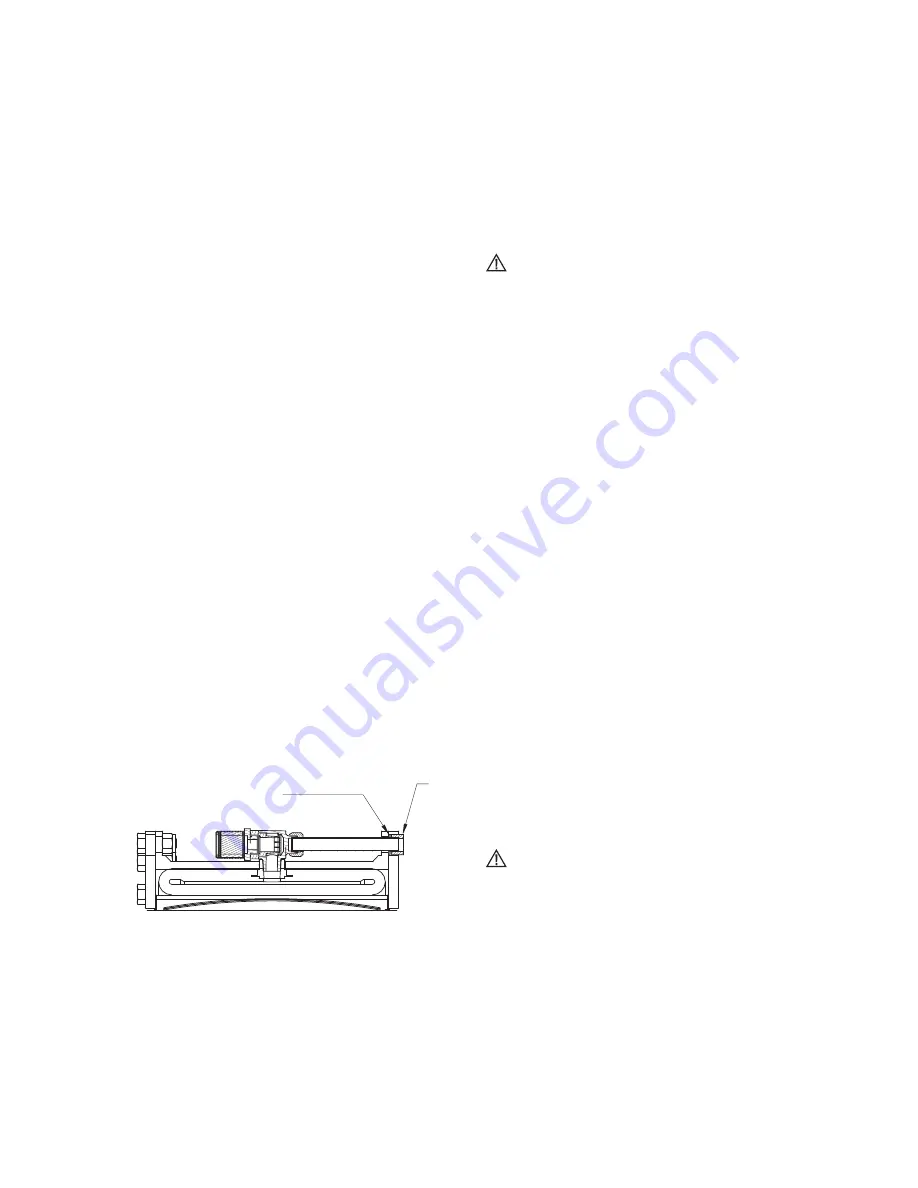
Install the air connection gaskets onto the air tubes.
The metal backup washer is to be positioned toward
the elbow (away from the spider). See Figure 9.
2.6.6
Align the element air connections with the passages
in the spider and attach the element to the spider
with the appropriate fasteners. See Table 1.
Make sure the element fully engages the register
in the spider.
2.6.7
Rotate the motor shaft and push the spider towards
the mill until the axial locking device mounting plate
is flush against the spider face and the motor is on
magnetic center. Attach the axial locking device
mounting plate to the spider with the appropriate
screws and lock washers. Tighten the screws.
Caution
Do not attempt to pull the motor shaft back onto
magnetic center by tightening the axial locking device
mounting screws. To do so will damage the axial
locking device.
2.7
Air control system
2.7.1
The typical TLC air control system(s) operating
charateristics vary from one grinding mill to another,
following are some general guidelines for installing
the air controls.
2.7.1.1 The air receiver tank(s) must be located as close to
the TLC as possible (the tank should be located
within 15 feet of the solenoid valve, and solenoid
valve should be within five feet from the rotorseal)
for consistent TLC response.
2.7.1.2 Use full size piping and valves consistent with the
rotorseal size and keep the number of elbows
to a minimum.
2.7.1.3 Use poppet-type solenoid valves. Spool valves should
not be used.
2.7.1.4 An air line lubricator is not required for the TLC
element; however, if one is used, it must be a
nonadjustable, mist-type.
2.7.1.5 Make sure the flow control valve is installed with free
flow (indicated by an arrow on the valve body) away
from the TLC (free flow to exhaust).
2.7.1.6 The final connection to the rotorseal MUST be made
with flexible hose and place no radial load upon the
rotorseal. Also, if the rotorseal is mounted onto the
end of a motor shaft, an insulating coupling must be
installed between the piping and the rotorseal.
Caution
Do not use rigid pipe at the connection to the
rotorseal. Rigid piping will result in excessive loads
on the rotorseal bearings, shortening life.
2.8
Electrical controls
2.8.1
The basic Airflex grinding mill TLC control provides
for engagement of the TLC when the motor is not
running and the mill is not turning. It also monitors
the TLC for slippage during operation and
disengages the TLC if slippage beyond the
allowable user set limits should occur. Refer
to the CP3130 TLC Slip control IOM for details.
Figure 9
Rubber backed washer
Steel Washer
Rubber
backing


