ANALOG INPUT MODULE
April 15, 1997
Page 3
8) Securing the Cover Plate. Before securing the
cover plate, check grounding and communication
connections.
Adjust the two cables from the IPONI so that they fit
under the cover plate. Line up the holes in the top of the
stand off screws used to secure the circuit board with
the holes in the plastic cover plate. Use the 1/4” nylon
screws to secure the cover plate. Do not overtighten.
9) Connecting Power. The AIM is powered by a UL-
listed, 24VAC, class 2, plug-in transformer rated at
24VA. Plug the transformer into any standard 120VAC
wall outlet. Attach the transformer connector to the
24VAC connector on the AIM to the left of the fuse
brackets on the upper right corner of the circuit board.
Note that the connector is keyed to fit in only one
direction.
Once power has been applied, the LEDs indicating
‘Logic Power’, ‘8VDC Power’ and ‘24VDC Power’ should
illuminate. Under normal operation the ‘Status’ LED will
flash about once a second. If a malfunction has
occurred, the ‘Status’ LED will remain lit. If the LEDs do
not illuminate in this fashion, refer to Step 12.
10) Connecting Sensors. Disconnect power from the
AIM before installing any sensor wiring. Failure to
disconnect power may result in electrical shock and/or
damage to the AIM.
The maximum allowable voltage to any channel input is
10 Volts. 24VDC power is available to power 4-20 mA
current loops. 8VDC power is available to monitor pulse
or runtime contacts. Refer to the specific sensor type
below for wiring diagrams.
Cable shields may be terminated at the AIM channel
ground terminals or at the sensor. In either case, shields
must be terminated at only one end.
4-20 mA Current Loop Sensors
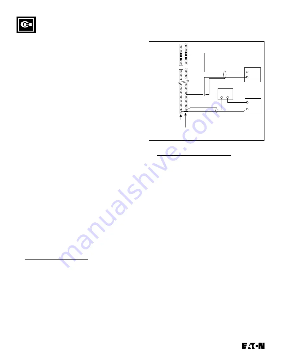
Figure 5 shows wiring connections for general purpose,
0-20 mA or 4-20 mA current loops. Sensors with this
signal output can be purchased from many
manufacturers to measure virtually any parameter,
including temperature, humidity, pressure and flow. The
AIM is equipped with a set of voltage source terminals
that provide 24VDC loop power, or these sensors can be
powered by an external source as shown in Figure 3. In
all cases, current loops must be grounded at the AIM.
AIM
Terminal
Blocks
32
31
30
29
11
10
9
8
7
6
5
4
3
2
1
24 VDC
Loop
Power
Channel Inputs
Channel Ground and
Shield Terminations
4-20mA Sensor
Powered by the AIM
4-20mA Sensor Powered by
an External Power Supply
External Power Supply
+
-
+
+
-
-
37
36
35
77
76
75
Figure 5 General Purpose Sensor Wiring
Pulse and Runtime Contact Sensors
Figure 6 shows the typical installation for pulse and
runtime contact sensors. Dry or isolated contacts must
be powered by a voltage source. Two voltages are
available at the AIM auxiliary terminals, 8VDC and
24VDC. If the 8VDC power is used, no resistor is
required. If the 24VDC power is used, install a 1,000
Ohm resistor in series with the dry contact to drop the
voltage down below 10 Volts.
Notes: 1) Input impedance is 499 ohms.
2) Pulse rates cannot exceed 10 pulses per
second, or 10Hz
3) Runtime contacts may be either normally
open or normally closed. The IMPACC
Series III software must be configured
accordingly.
There is enough power on the auxiliary terminals to
drive all 32 inputs using the method shown in Figure 6.
If the 24VDC loop power is used, the total maximum
power draw off of the 8VDC and 24VDC power terminals
combined cannot exceed 16VA.


