


UPS System Installation
Eaton 93PM UPS (20–50 kW, 480V Four Wire – 50 kW Frame) Installation and Operation Manual P-164000540—Rev 4
www.eaton.com/powerquality
4-31
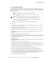
Figure 4-24. REPO Switch
11. Route the REPO wiring through the bottom interface entry conduit landing plate to the bottom access
interface wiring channel along the inside of the front door (see Figure 4-11).
12. Route the wiring along the interface wiring channel (see Figure 4-11) to the REPO terminals. See
Figure 4-9 and Figure 4-10 for UPS interface terminal locations.
13. Secure the wiring to the wire tie anchors provided (see Figure 4-12) using Zip ties.
14. Connect the REPO wiring as shown in Table 4-7 and Figure 4-26 for a normally-open REPO, or Table 4-8
and Figure 4-27 for a normally-closed REPO. See paragraph 3.2.4 for wiring and termination requirements,
and Figure 4-25 for terminal assignments.
15. If using a normally-closed REPO switch, connect a jumper wire between pins 3 and 4 on the REPO
terminal block.
16. If you are installing multiple REPO switches, wire additional switches in parallel with the first REPO.
17. If required, install wiring from the REPO switch to the trip circuitry of the upstream protective devices. A
second contact block is provided on the REPO switch for this function (see Figure 4-24). The REPO switch
wiring must be in accordance with NEC Article 725 Class 2 requirements.
18. Close the UPS outside door and secure the latch.
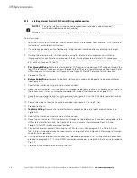
Figure 4-25. REPO Terminal Block Connector Assignments
REPO Switch (Front View)
Contact Block (Back View, Faceplate Removed)
Normally Closed
REPO Contacts
Normally Open
REPO Contacts
UPS REPO
1
2
3
4
GND-I
S
O
EPO_A_B
EPO_B
EPO_A
Summary of Contents for 93PM UPS
Page 1: ...Eaton 93PM UPS 20 50 kW 480V Four Wire 50 kW Frame Installation and Operation Manual...
Page 2: ......
Page 3: ...Eaton 93PM UPS 20 50 kW 480V Four Wire 50 kW Frame Installation and Operation Manual...
Page 25: ...Section 1 Installation...
Page 26: ......
Page 87: ...Section 2 Operation...
Page 88: ......
Page 145: ......
Page 146: ...P 164000540 4 P 164000540 4...


