UPS Installation Plan and Unpacking
3-10
Eaton
®
Power Xpert
®
9395C UPS Installation and Operation Manual
P-164000821—Rev 01
www.eaton.com/powerquality
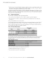
If the power rating listed on the nameplate of the installed UPS is not found in the following tables, wire the
UPS using the fully rated specifications. Otherwise, calculate the required wire, conduit, and breaker sizes
using the following guidelines in addition to those already listed in paragraph 3.2.3:
l
Select wire size according to the UPS nameplate.
l
Do not use wire larger than the largest size listed in Table 3-4.
l
Use terminal recommendations from Table 3-4.
l
Size and number of conduits must not exceed those listed in Table 3-10.
l
Select overcurrent protection input, battery, and output breakers according to the UPS nameplate rated for
either 80% or 100%.
l
Follow all applicable NEC and local codes.
ommended
installations using a common battery system. Wire sizes listed are for copper wiring only.
NOTE
V
Callout letters
A
,
B
,
C
, and
D
Battery Conductor Sizing
: Eaton strongly recommends using the specified DC conductor size and quantity shown above for optimum system
performance and battery run time.
Battery Cable Routing Requirements
Conduit applications:
* Each conduit must have a Positive, Negative, and Ground conductor.
* There must be an equal number of positive and negative conductors in a single conduit. Only one ground conductor is required in each conduit.
Raceway applications:
* Positive and negative battery cables must be run side by side in the raceway in an alternating pattern (+ - + - + - + -).
* There must be a ground cable running in the raceway with the battery cables.
Table 3-4. 480VInput/Output Ratings and External Wiring Requirements
Basic Unit Rating
Units
Rating
50/60 Hz
Rating
50/60 Hz
Rating
50/60 Hz
kW
kVA
1000
1000
1000
1100
1100
1100
Input and Output Voltage
Volts
480/480
480/480
480/480
AC Input to UPS Rectifier (0.98 Minimum pF)
Full load current plus battery recharge current
(3) Phases, (1) Ground
A
Amps
1485
1485
1600
Recommended Conductor Size
Number per Phase
kcmil
(each)
500
(5)
500
(5)
500
(6)
AC Input to UPS Bypass
Full Load Current
(3) Phases, (1) Ground
B
Amps
1203
1323
1323
Recommended Conductor Size
Number per Phase
kcmil
(each)
500
(5)
500
(5)
500
(5)
DC Input from Battery Disconnect to UPS
(1) Positive, (1) Negative
C
Amps
2193
2193
2412
Recommended Conductor Size
Number per Pole
(1) Positive, (1) Negative
kcmil
(each)
500
(10)
500
(10)
500
(12)
AC Output to Critical Load
Full Load Current
(3) Phases, (1) Ground=
D
Amps
1203 1323
1323
Conductor Size
Number per Pole
kcmil
(each)
500
(5)
500
(5)
500
(5)
Summary of Contents for 9395C-1000/1000
Page 2: ......
Page 23: ...Section I Installation ...
Page 24: ......
Page 93: ...Section II Operation ...
Page 94: ......
Page 155: ......
Page 156: ... P 164000821 1 P 164000821 1 ...


