


1 0
1 0
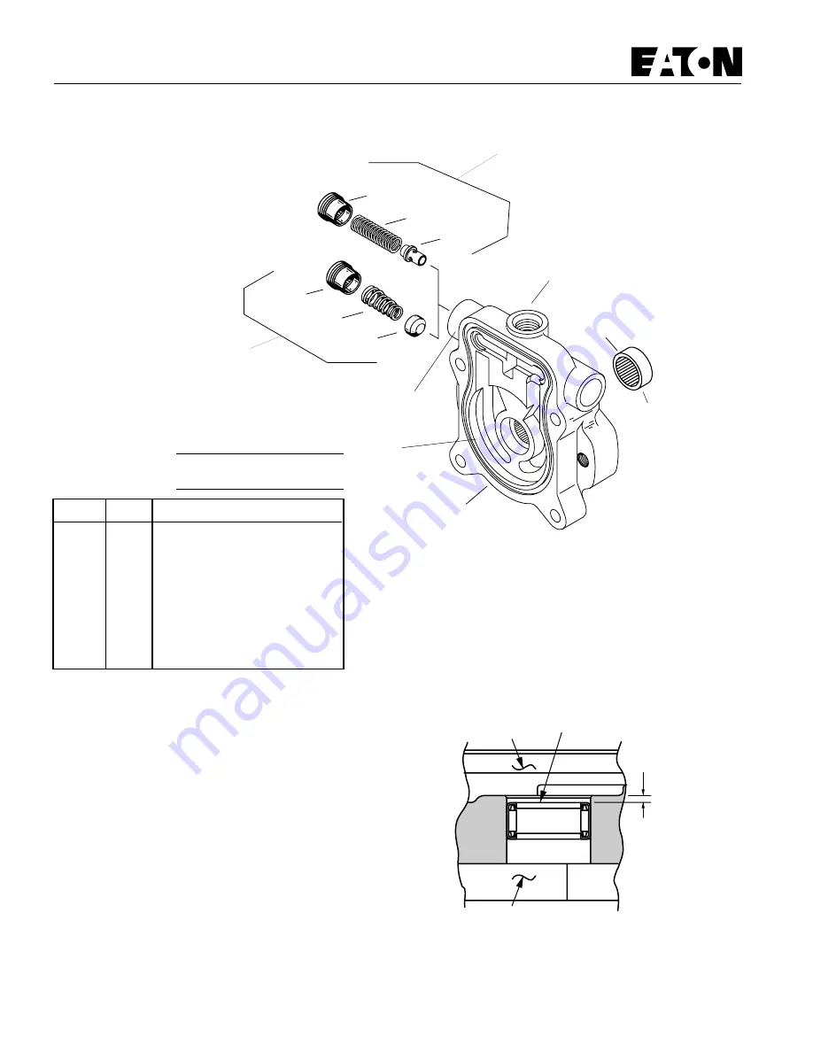
Model 70142 and 70145
Appendix A -
Charge Pump Adapter Assembly
36-4
36-3
36-1
36-2
Gerotor Ring
Pocket
(See chart for
depth)
Bearing
36-4a
36-3a or 3b
36-2a
Configuration for
6.9 to 1.3 bar
[100 to 150 lbf/in
2
]
Charge Relief Valve
36
Charge Pump
Suction Port
Pressure Check Port or
Remote Charge Port
Configuration for
13.8 to 17.2 bar [200 to 250 lbf/in
2
] or
17.2 to 20.7 bar [250 to 300 lbf/in
2
]
Charge Relief Valve
Reassembly -
Charge Pump Adapter Assembly
1
If necessary, press new bearing in adapter assembly. The
bearing to dimension shown in figure 1-2 with the numbered
end of bearing outward and closest to mounting flange.
2
Install cup poppet or pin poppet, spring, and spring
retainer into charge pump adapter. Torque retainer 6.8 to 9.5
N
.
m [5 to 7 lbf
.
ft.]
Numbered End
Gerotor Pocket
2.41 mm
[.095 in.]
Flange
Figure 1-2
Disassembly -
Charge Pump Adapter Assembly
1
Remove
spring retainer
, spring, and poppet from adapter
assembly.
Inspection:
• Inspect the charge pump relief valve seat inside the
charge pump adapter. Check to insure that seat is smooth and
free of burrs or other defects.
• Inspect the charge pump relief valve spring.
• Inspect the bearing inside the charge pump adapter.
The bearing needles must remain in the bearing cage and
bearing at dimension shown in figure 1-2.
• Inspect the gerotor pocket inside the charge pump
adapter assembly. It should not be scored excessively.
Item
Qty.
Description
36
1
Charge Pump Adapter Assy.
36-1
1
Bearing (press fit)
36-2
1
Poppet, Cup
36-2a
1
Poppet, Pin
36-3
1
Spring, Tappered
36-3a
1
Spring, "Light Green" *
36-3b
1
Spring, "Pink" **
36-4
1
Spring Retainer
36-4a
1
Spring Retainer
*
200 to 250 lbf/in
2
**
250 to 300 lbf/in
2
Gerotor Pocket Depth
Displacement
Depth of Pocket
cm
3
/r [in
3
/r]
mm [in.]
6.9 [.42]
6.35 [.25]
13.8 [.84]
12.7 [.50]