


Instruction Book
Effective: November 2017
Page 23
IB131016EN
For more information visit:
www.Eaton.com
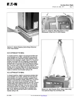
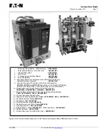
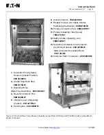
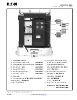
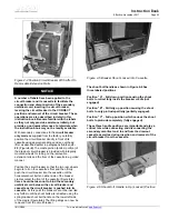
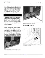
Figure 4-1 Typical Fixed Non-Automatic VCP-TR
15KV Circuit Breaker
A 5a, 5b auxiliary switch with double break, wipe type
contacts is provided as standard for customer use.
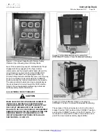
4-6 INSTALLING DRAWOUT CIRCUIT BREAKER
VCP-T circuit breakers are installed in structures
equipped for drawout circuit breakers. A bolted-in
drawout cassette supports the circuit breaker (Figures
3-7
and
3-9).
4-6.1 DRAWOUT MECHANICAL INTERFACES
Each drawout circuit breaker is supplied with the
following interlocks to insure safe and proper operation.
Rejection Interlocks
Rejection interlocks are steel pins mounted at the bottom
of the drawout circuit breaker and in the base tray (floor)
of the cassette to prevent the insertion of a circuit
breaker into a structure with a higher power rating. The
pins are factory mounted in the circuit breaker.
It is the
customer’s responsibility to correctly mount the pins
in the drawout cassette.
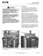
WARNING
DO NOT DISABLE REJECTION INTERLOCKS.
DOING SO AND USING A CIRCUIT BREAKER IN A
STRUCTURE WITH A HIGHER POWER RATING
COULD RESULT IN AN ELECTRICAL FAULT WHICH
COULD RESULT IN DEATH, BODILY INJURY
AND/OR EQUIPMENT DAMAGE.
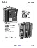
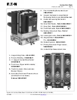
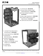
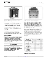
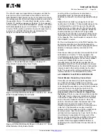
Figure 4-2 Bottom View of VCP-TR Circuit
Breaker showing Mounting Holes
As the circuit breaker is pushed into the structure, the
mating pins on the bottom of the circuit breaker move
past a set of corresponding pins in the cassette, if the
circuit breaker and cassette are compatible. If there is a
mismatch between the circuit breaker and the cassette,
the rejection pins prevent the circuit breaker from being
fully inserted into the cassette.
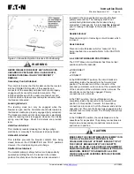
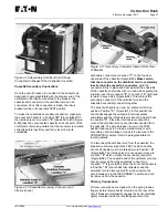
Before attempting to position the circuit breaker for
insertion into its cassette, compare the positioning of the
rejection interlock pins in the cassette in keeping with
Table
4.1
and Figure
4-3
and ratings information
supplied on the circuit breaker’s nameplate. Proceed if
the circuit breaker and cassette are compatible. If they
are not compatible, do not attempt to insert the circuit
breaker into the cassette. Contact Eaton for assistance
if required.
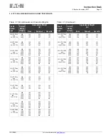
Table 4.1 Cassette Rejection Interlock Pin Locations
Cassette Used For
Pin Locations
1 2 3 4 5 6 7 8 9
Short Circuit Rating (kA)
16 0
0
0
20 0
0
1
25 0
1
1
31.5/40 1
1
1
Current Rating (A)
600
0 0 0
1200
1 1 0
1600/2000/2500
1 1 1
Rated Voltage (kV)
4.76
0
0
8.25
0
1
15.0
1
1
Type
Dummy Element
0
Circuit Breaker
1
0 = no pin required, 1 = pin required
Rejection Pin-Kit 68B3049G01
Summary of Contents for 50 VCP-TR16
Page 2: ......


