


-43-
3.2 Parallel machine installation
1. Redundancy introduction
N+X is currently the most reliable power supply structure, in which N indicates the
minimum UPS number required for the total load and X is the redundant UPS number,
namely, the malfunctioning UPS number that the system can simultaneously bear. The
larger X is, the higher reliability of system will be. For instance, if the total loads of a
customer register 55kVA, we can use Castle 20KS for N+X design. With N taking up
3, X can be selected in accordance with reliability degree or cost requirement.
Supposing customer selects X=2 and equalized UPS power supply is 11kVA for each
unit, when one set of UPS breaks down with malfunction, the remaining four sets will
provide power with almost 14kVA equalized current; if two sets of UPS fail, the
remaining three sets of UPS are supposed to provide power supply with almost 18kVA
equalized current. The maximum allowance of this system is for two sets of UPS
going down at the same time, the chances of which are much smaller than those of
one UPS malfunction. Therefore, the reliability degree can be largely enhanced,
making it an optimal mode for application in locations where high degree of reliability
is always a focus.
2. Castle EX Series UPS is capable of direct parallel connection, which only requires
the parallel
connection wires (optional) for 2 to 8 sets of UPS in parallel connection in order to
realize power redundancy (N+X). Ventilation spacing between machine flanks should
be a minimum of 10cm
,
input wiring for each set of UPS should follow the
requirements for that of single unit. Each UPS input/output should be connected to the
same input patch board, from which wires are distributed for load as illustrated in
following figure:
Remark:
1
)
Common battery pack is applicable in parallel machine mode; each battery pack
should be of the same model from the same manufacturer.
2)
Requirement of output wiring length:
Summary of Contents for 3C3-EX Series
Page 3: ...3 1 2 3 4 5 UPS 6 7 8 1 2 UPS UPS 10 UPS 3 1 UPS 2 3 4...
Page 4: ...4 A B C D E 5 6 7 1 A 0 40 20 90 B C 2 UPS 25 55 UPS 0...
Page 6: ...6 1 2...
Page 8: ...8 2 3 LCD LCD UPS UPS UPS UPS LCD LCD UPS UPS UPS UPS LCD UPS...
Page 9: ...9 LCD LCD Esc LED UPS...
Page 11: ...11 7 EX UPS 14 16 12VDC 168VDC 192VDC 8 19...
Page 12: ...12 9 9 1 3 4W 3 4W 1 380V 220V 3 4 1 2 N G 2 3 4 1 3 3 UPS 2 N G 3 4W 20kVA 40kVA...
Page 17: ...17 1 2 UPS 20 20 UPS 20 10 3...
Page 18: ...18 3 3 UPS 1 UPS 2 3 N UPS 4 UPS N N...
Page 19: ...19 4 1 1 R S T UPS 2 Turn ON UPS N N 3 UPS Turn ON UPS 4 3C3 20KVA EX 1 2 4 3 ESC 1 4...
Page 20: ...20 5 6 7 8 L C D L C D...
Page 21: ...21 4 ESC 1 2 ENTER 3 4 5...
Page 22: ...22 5 ESC 1 2 3 4 ENTER 5 6 U P S...
Page 23: ...23 6 1 2 ENTER 3 ENTER...
Page 24: ...24 7 ESC 1234 1 2 3 ENTER 4 ENTER...
Page 25: ...25 8 EX UPS UPS N UPS Turn ON ENTER LCD 40...
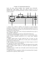
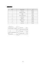
Page 27: ...27 7 RS485 UPS UPS RS485 8 SERVICE 9 RS232 WinPower RS232 RS232 PORT...
Page 28: ...28 RS485 PORT AS400 PORT...
Page 29: ...29 UPS UPS 1 UPS 2 UPS 3 UPS EX UPS 1 2 A UPS NFB OFF B C D 3 4 UPS 1 UPS 2...
Page 30: ...30 3 LED LCD UPS UPS 8...
Page 33: ...33...
Page 46: ...46...
Page 47: ...47...
Page 48: ...48...
Page 49: ...49...
Page 52: ...52 RS232 PORT RS485 PORT...
Page 53: ...53 AS400 PORT...


