


3
Instruction Leaflet
IL2C13761H11
Effective March 2020
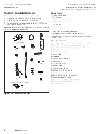
Installation instructions for Kirk
Key Interlock Kit (2C12891G21) in
Magnum low-voltage circuit breakers
EATON
www.eaton.com
Section 2: Installation of key locks
Proceed with the following 14 steps:
IMPORTANT
DO NOT REINSERT KEY UNTIL STEP 6.
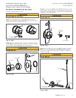
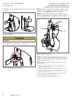
Step 1:
First remove key from key lock
(A)
. Then remove two
screws from back of key lock and discard the cam arm and screws.
Remove one knurled nut from barrel of lock.
Cam arm (to be
removed)
Knurled nut
Figure 2. Step 1
Step 2:
Remove second knurled nut from key lock body and place
bushing
(B)
on cylinder body. Note orientation of key lock, and then
mount to lock mounting plate
(C)
with the knurled nut.
IMPORTANT
DO NOT INSERT KEY.
Key lock
(A)
Bushing
(B)
Knurled nut
Kirk lock mounting
plate
(C)
Figure 3. Step 2
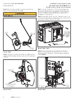
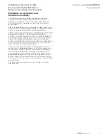
Step 3:
Put torsion spring
(D)
on guide pin
(E)
. Note the orientation
of spring legs, and carefully press the knurled end of guide pin into
hole in key lock body to the depth of the knurl. This step requires an
Arbor press, vise, or equivalent.
IMPORTANT
DO NOT INSERT KEY.
Key lock
Torsion
spring
(D)
Guide pin
(E)
Figure 4. Step 3
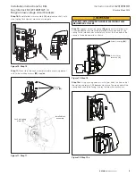
Step 4.
Mount cylinder interlock adapter
(F)
to hexagonal standoff
(G)
with 1/2 inch long cap head screw
(H)
and tighten securely.
Attach cable assembly
(I)
to other end of hexagonal standoff with
shoulder screw
(J)
.
IMPORTANT
DO NOT INSERT KEY.
Hex standoff
(G)
Cable assembly
(I)
Cap screw
(H)
Cylinder interlock
adapter
(F)
Shoulder
screw
(J)
Figure 5. Step 4