background image

9

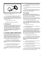
Spirolox Ring (31)

Hooked Tool

Figure 6.  Removing Spirolox Ring

10. Pull the shaft group (24 through 26) from the body

(29). If the bearing (25) or shaft (26) needs replacement,
remove retaining ring (24) and press the bearing off the shaft
with an arbor press. Apply pressure to the inner race of the
bearing during removal.

11. Remove washer (27) from body.

12. Drive the shaft seal (28) out of body (29).

D. Cleaning 21.

All parts must be thoroughly cleaned and kept clean during
inspection and assembly. Contamination in the unit will
cause excessive wear, leakage and decreased service life.
Use a commercial solvent which is compatible with the
system fluid. Thoroughly clean all parts. Drying parts with
compressed air after cleaning is not recommended unless
the air is completely filtered to remove water and
contamination.

E. Inspection, Repair & Replacement

Check that all internal passages are clean and unobstructed.
Examine all mating surfaces for nicks and burrs. Check
locating pins and holes for wear and burrs. Check the
condition of threaded parts and threaded holes. Check all
retaining ring recesses. Minor burrs can be removed with an
India stone. Replace any part that shows wear or damage.
The following parts are subject to special attention.

1. Cartridge Kit (11). In order to obtain maximum

overhaul life of the pump, a complete cartridge kit should be
installed if wear or scoring is noticed during the following
steps.

a.  Inspect the mating surfaces of the rotor (20),

outlet support plate (22) and inlet support plate (17).

b.  Inspect the vanes and intra-vanes (21) for burrs,

wear and play in the rotor (20) slots. The intra-vanes should
not bind in the vanes. Remove minor burrs with an India
stone.

c.  Inspect bushing for wear and scoring. Wear on

one side indicates that the pump and drive motor were not
aligned. See Figure 4.

2. Check bearing (25) for wear, looseness and pitted or

cracked races.

3. Inspect the seal and bushing mating surfaces on

shaft (26) for scoring and wear. Replace the shaft if marks
cannot be removed by light polishing.

F. Assembly

Refer to parts and service drawing listed in Table 1 for
replacement parts. Always replace old seals with new seals
when overhauling a unit. If a cartridge kit needs replacing,
new seals are included in the cartridge kit.

Apply a light film of hydraulic fluid to all component parts to
facilitate assembly and provide initial lubrication. Install parts
in reverse order of disassembly. See Figure 8.

1. Install shaft seal (28) into body (29) so that the

spring in the seal faces the inside of the pump. Press the
shaft seal into the body. Use shaft seal tool shown in Figure
5 and an arbor press.

2. Install washer (27) into body.

3. If required, press bearing (25) on to shaft (26) and

secure with retaining ring (24).

4. Recheck shaft key way for nicks and burrs that could

cut the shaft seal. Remove burrs. Thoroughly lubricate the
key way end of shaft and shaft seal lip with hydraulic oil.
Carefully install shaft group (items 24 through 26) through
the seal and into body (29). Spread the spirolox ring (23) and
feed it into the groove located behind the bearing. This will
secure the shaft group within body (29).

5. Assembly sealing ring (14) into body (29).

6. If a new cartridge kit is required, install new cartridge

kit (11) on the shaft and into the body (29). If cartridge kit
assembly is required, assemble in the reverse order of
disassembly. During assembly, note the following
precautions;

a.  Make sure the rotation arrows on ring (19) and

rotor (20) point in the direction of rotation.

b.  Be certain the sharp edges of vanes (21) lead in

direction of pump rotation. See Figure 7.

c.  Make sure “O” ring (12) and back-up ring (13) are

positioned correctly as shown on Figure 8.

7. Apply a small amount of hydraulic fluid on threads of

two screws (16). Thread the screws into cartridge kit. Install
cartridge kit (11) on the shaft and into body (29).

Summary of Contents for 20 Design 282 Series

Page 1: ...I 3157 S Reprinted 6 1 96 Quiet Intra Vane Single Pumps 25V T 35V T 45V T Series 20 Design 282 283 Series Service Data Vickers Vane Pumps ...

Page 2: ...ft Rotation 5 D Piping and Tubing 5 E Hydraulic Fluid Recommendations 5 F Sound Levels 6 G Overload Protection 6 H Start Up 6 V Service Maintenance A Circuit Inspection 6 B Adding Fluid to the System 6 C Adjustments 6 D Lubrication 6 E Replacement Parts 6 F Product Life 7 G Troubleshooting 7 VI Overhaul A Service Tools 8 B Unit Removal 8 C Disassembly 8 D Cleaning 9 E Inspection Repair and Replace...

Page 3: ...talog Installation 25V I 3158 S 25VT I 3154 S 35V I 3177 S 560 35VT I 3149 S 560 45V I 3159 S 45VT I 3151 S Table 1 Related Publications Model Code 2 2 4 5 6 7 8 9 10 11 1 Viton seals 1 3 12 3 Pump series Quiet intra vane type pump 4 Omit if not required Thru shaft connection mtg SAE 2 bolt adapter flange 5 SAE rated delivery USgpm 1200 RPM at 100 PSI A A flange B B flange C C flange 6 Port connec...

Page 4: ... rotor turns Centrifugal force and pressure under the vanes hold them out against the cam ring Pumping chambers are formed between the vanes and the cam ring and are enclosed by the two support plates The 282 283 series pumps are of a balanced intra vane design see Figure 2 Outlet pressure is constantly applied to the small intra vane area of the vane As the pump vane rotates through the high and ...

Page 5: ...s in tubing should be kept to a minimum to prevent excessive turbulence and friction of oil flow Tubing must not be bent too sharply The recommended minimum radius for bends is three times the inside diameter of the tube E Hydraulic Fluid Recommendations 9 General Data Fluid in a hydraulic system performs the dual function of lubrication and transmission of power It constitutes a vital factor in a...

Page 6: ...ystem resulting in noisy and or erratic operation 2 Clean fluid is the best insurance for long service life Therefore the reservoir should be checked periodically for dirt or other contaminants If the fluid becomes contaminated the system should be drained and the reservoir cleaned before new fluid is added 3 Filter elements also should be checked and replaced periodically A clogged filter element...

Page 7: ...and operate system until purged Bleed hydraulic lines at highest point down stream of pump while system is under pressure Vacuum condition Check inlet suction line and fittings for air leaks Oil too thick Be certain correct type of oil is used in system Warm up pump in cold weather until noise disappears Damaged or missing pump seals at mating surfaces Locate and replace damaged or missing seals C...

Page 8: ...f hydraulic oil source to pump inlet if an overhead reservoir is used 2 Remove the unit from the system 3 Cap all system and unit openings to prevent entry of dirt or moisture C Disassembly The index numbers on Figure 8 are in order of the disassembly sequence 1 Thoroughly clean pump exterior 2 Use a prick punch and mark the position of cover 4 with respect to the body 29 Mark position of the flan...

Page 9: ...eck bearing 25 for wear looseness and pitted or cracked races 3 Inspect the seal and bushing mating surfaces on shaft 26 for scoring and wear Replace the shaft if marks cannot be removed by light polishing F Assembly Refer to parts and service drawing listed in Table 1 for replacement parts Always replace old seals with new seals when overhauling a unit If a cartridge kit needs replacing new seals...

Page 10: ...ct adapter flange 6 to inlet cover 4 with four screws 5 NOTE Lockwashers are used with screw 5 for C adapter flanges only Torque screws 5 to specifications noted in Table 5 Screw 5 Torque Specifications Model Adapter Flange N m lb ft 25VT 35VT A or B 54 68 40 50 45VT 35VT C 31 40 23 30 45VT C 31 40 23 30 Table 5 Screw 5 Torque Specifications 11 Install key 2 on shaft 26 12 Place pump into mounting...

Page 11: ...ket Kit Key Screw Cover Screw Adapter Flange O Ring Spline Coupling Retaining Ring Screw Cartridge Kit items 12 22 Back up Ring O Ring Sealing Ring O Ring 1 1 4 1 4 1 A R 1 1 4 1 1 1 1 1 Item Nomenclature Qty 16 17 18 19 20 21 22 23 24 25 26 27 28 29 Screw Inlet Support Plate Pin Ring Rotor Vanes Intra Vanes Outlet Support Plate Spirolox Ring Retaining Ring Bearing Shaft Washer Shaft Seal Body 2 1...

Reviews: