10
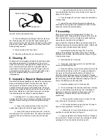
Inlet
Direction of
rotation
Rotor
Sharp edges
lead direction
of rotation
Vane
Ring
Figure 7. Positioning Vanes in Rotor
8. Install “O” ring (15) over the cartridge kit (11) and into
the body “O” ring groove.
9. Line up the two cartridge pins (18) with the holes in
cover (4). Assemble cover (4) over cartridge kit and up
against body face. Position cover (4) according to markings
made during step C-2 of the disassembly procedure. Secure
the cover with four screws (3). Torque screws (3) to
specifications noted in Table 4.
Screw (3) Torque Specifications (Figure 8)
Model
N.m
lb. ft.
25V
88–101.6
65–75
35V
190–217
140–160
45V
345–372.8
255–275
Screw (10) (Figure 8)
25VT
88–101.6
65–75
35VT
190–216.9
140–160
45VT
345–359
255–275
Table 4. Torque Specifications for Screw (3)/(10)
a. Line up the two cartridge kit pins (18) with the
holes in inlet cover
b. Install spline coupling (8) on end of shaft (26).
NOTE
If a new shaft and coupling kit is required,
install retaining ring (9) into coupling (8) prior
to coupling installation.
c. Install “O” rings (7) on both sides of adapter
flange (6).
d. Connect adapter flange (6) to inlet cover (4) with
four screws (5). (NOTE: Lockwashers are used with screw
(5) for ‘C’ adapter flanges only.) Torque screws (5) to
specifications noted in Table 5.
Screw (5) Torque Specifications
Model
Adapter Flange
N.m
lb. ft.
25VT
35VT
“A” or “B”
54–68
40–50
45VT
35VT
“C”
31 40
23 30
45VT
“C”
31–40
23–30
Table 5. Screw (5) Torque Specifications
11. Install key (2) on shaft (26).
12. Place pump into mounting bracket (1) and secure it
with the two mounting bracket screws.
Section VII – Start-Up and Test
A. Start-Up 22.
Install the unit into the system. Make sure the drive shaft is
aligned properly. Be sure all connections are tight and the
hydraulic fluid source is open to pump inlet before start-up.
The pump should prime almost immediately with a minimum
drive speed of 600 RPM. Intermittently operate (jog) the
pump until it primes. It may be necessary to loosen the outlet
fitting temporarily to purge trapped air. Failure of the pump to
prime in a short period of time indicates incorrect assembly
or restricted flow from the reservoir.
B. Test
Use your hydraulic system to test the unit. Refer to the
installation drawings listed in Table 1 for recommended
speeds and pressures. If more precise testing is desired,
consult your Vickers sales engineering office.


