background image

Replacement Parts

ITEMS

DESCRIPTION

EATON STYLE NUMBER

MOTOR CUTOFF SWITCH

QUICK DISCONNECT

RING TERMINALS

699B199G01

699B199G04

 WARNING

VERIFY CIRCUIT BREAKER IS OPEN, CLOSING SPRINGS ARE 

DISCHARGED AND CONTROL POWER IS DISCONNECTED. 

REFERENCE: THE SPRING RELEASE COIL IS THE COIL ON THE 

LEFT SIDE, LOOKING INTO THE CIRCUIT BREAKER, WITH 

THE GREEN “PUSH TO CLOSE” LABEL. THE SHUNT TRIP 

COIL IS THE COIL ON THE RIGHT SIDE, LOOKING INTO THE 

CIRCUIT BREAKER, WITH THE RED “PUSH TO OPEN” LABEL.

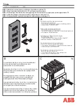
Adjustment of the Motor Cutoff Switch 

With the circuit breaker in the open and discharged 

state, remove the front cover.
Manually charge the circuit breaker, making sure to use 

full and complete strokes of the charging handle. The 

switch arm must drop on the last charging stroke, and 

not bend when the motor cut-off cam returns to the 

normal position.
With a small flat-head screwdriver, slowly raise the 

straight arm of the switch assembly. The bent arm of 

the second switch should rise at the same time as the 

straight arm. Both switches should change state at 

approximately the same position, and when the straight 

arm is approximately half way between the low and 

high positions of the motor cutoff cam. The change of 

the state of the switches can be determined by a pair of 

audible “clicks”.
Adjustment: If the switch with the straight arm changes 

state outside of the target region, the switch assembly 

can be removed, the switch mounting screws can be 

loosened and the switch position may be adjusted as 

necessary. Care should be taken to not bend the straight 

switch arm unless absolutely necessary to correct 

misalignment caused by physical damage to the switch 

arm. Re-install the switch assembly and verify that the 

switch with the straight arm changes state inside of the 

target region.
Verify that both switches change state at approximately 

the same position.
If the switch with the bent arm changes state outside 

of the target region between the low and high positions 

of the motor cutoff cam, the bent switch arm may be 

adjusted by gently bending the arm until both switches 

operate at approximately the same position.
Verify the electrical operation of the motor, making sure 

that the motor circuit cuts off at the appropriate time.
If during an electrical charging operation the camshaft 

fails to rotate far enough for the motor cutoff switches 

to actuate, the charging pawls may require adjustment.

Component

Adjustment

Testing the motor cutoff switch for adjustment on a 150VCP-W25 mechanism.

Return the circuit breaker to a discharged and open 

state. Remove all control power from the circuit breaker.
Manually charge the circuit breaker half-way. Raise the 

manual charging bar and hold it in the upper position.
Using a pair of needle-nose pliers, grip the pin of the 

charging pawl located just below the charging gear 

mounted below the manual charging bar insertion point. 

Pulling the pin of the charging pawl toward you will 

rotate the pawl away from the charging gear. Hold the 

charging pawl away from the charging gear.
Gently lower the manual charging bar.
Gently let the charging pawl return to rest on the 

charging gear.
Using a feeler gage, measure the gap between the 

top of the charging pawl and the closest tooth of the 

charging gear. The gap should be between .045 and 

.090 inches.
If this gap needs to be adjusted:
Locate the stop bracket. The stop bracket is a steel 

angle just to the right of the manual charging bar 

insertion point, secured to the right hand mechanism 

side sheet with two bolts.
Using two ½ inch combination wrenches or socket 

wrenches, slightly loosen the stop bracket bolt at the 

front of the mechanism. Do not completely loosen or 

remove this bolt. The bracket will pivot on the rear bolt, 

but the front bolt must continue to provide enough 

friction to hold the bracket in position.
Using a flat–head screwdriver, lower (or raise as 

necessary) the position of the front of the stop bracket 

slightly.
Tighten the stop bracket bolt at the front of the 

mechanism.
Complete the charging of the circuit breaker. Close and 

open the circuit breaker and repeat steps 9-13 until the 

gap between the charging pawl and the closest tooth of 

the charging gear is within the specified range.
Re-verify the electrical operation of the motor, making 

sure that the motor circuit cuts off at the appropriate 

time.

13

EATON


|


Visual Instruction Booklet Essentials   |   150VCP-W 25kA 1200A   |   January 2017  

Summary of Contents for 150VCP-W Series

Page 1: ...A January 2017 Supplemental Material For 15kV VCP W This is a user interactive supplemental booklet This material is intended to enhance the technical information included in the instruction booklet for the 15kV VCP W circuit breaker manufactured by Eaton Supplemental Material For 15kV Element ...

Page 2: ...e permitted to work on these circuit breakers Always remove the circuit breaker from the enclosure before performing any maintenance Failure to do so could result in electrical shock leading to death severe personnel injury or property damage Do not work on a circuit breaker with the secondary test coupler engaged Failure to disconnect the test coupler could result in an electrical shock leading t...

Page 3: ...m Interrupter Assembly Each interrupter is assembled at the factory as a unit to assure correct dimensional relationships between working components The interrupter assembly consists of a vacuum interrupter a molded glass polyester stand off insulator upper and lower clamps flexible shunts bell crank operating rod and contact load spring The vacuum interrupter is mounted vertically with a fixed st...

Page 4: ... POTENTIAL TESTS ARE NOT RECOMMENDED BY EATON DO NOT APPLY DC AT ANY LEVEL TO VCP W POWER CIRCUIT BREAKERS With the circuit breaker open and securely sitting on the floor connect all top front primary studs bars together and the high potential machine lead Connect all bottom rear studs together Do not ground them to the circuit breaker frame Start the machine at zero potential increase to appropri...

Page 5: ...ELL BELOW MAXIMUM PERMITTED BY STANDARDS HOWEVER AS A PRECAUTIONARY MEASURE AGAINST POSSIBILITY OF APPLICATION OF HIGHER THAN RECOMMENDED VOLTAGE AND OR BELOW NORMAL CONTACT SPACING IT IS RECOMMENDED THAT ALL OPERATING PERSONNEL STAND AT LEAST ONE METER AWAY IN FRONT OF THE CIRCUIT BREAKER Insulation Integrity Test Note N Roll over each high potential test diagram configuration above to see the co...

Page 6: ...rminal of the phase being tested 8 Press the TEST button on the DLRO Once the TEST button is pressed 100A dc will flow through the phase being tested If the circuit breaker is not closed the DLRO will not inject current 9 Apply the DLRO positive measurement test lead to the TOP terminal Be mindful not to connect this measurement lead to the current lead This insures that the current lead is not be...

Page 7: ...mount of motion to the operating rods The first portion of the motion is used to close the contacts i e stroke and the remainder is used to further compress the preloaded wipe spring This additional compression is called wipe Wipe and stroke are thus related to each other As the stroke increases due to the erosion of contacts the wipe decreases A great deal of effort and ingenuity has been spent i...

Page 8: ...rcuit breaker several times manually and electrically Roller bearings are used on the pole shaft the cam shaft the main link and the motor eccentric These bearings are packed at the factory with a top grade slow oxidizing grease which normally should be effective for many years They should not be disturbed unless there is definite evidence of sluggishness dirt or parts are dismantled for some reas...

Page 9: ... the eccentric counterclockwise use a wooden hammer handle to break the threads Remove the two screws on the right hand motor support plate using a 9 64in Allen wrench Remove the motor plate from the side sheet for the 5kV circuit breaker Remove the motor Verify the new motor has the correct motor voltage on the motor sticker Lubricate the motor threads using molybdenum disulfide grease Eaton No 5...

Page 10: ...ead bolt lock washer and spacer that hold the coil in place Be careful to capture the two fiber insulating washers behind the coil Note N The 5 16 x 3 in bolt is made of silicon bronze for magnetic purposes and must never be replaced with a steel bolt Slide the coil out of its bracket to its available open side and feed the wires through Remove the metal core from the center of the coil Install ne...

Page 11: ...of wires make sure 2nd Shunt trip wires route the same way Place aluminum shim on back of 2nd shunt trip as shown Hold shim in place while you begin installation Make sure wires are routed through the same opening as the existing Install 2nd Shunt Trip next to existing Push to Open Assembly as shown hand tighten center bolt Make sure aluminum shim does not fall out Make sure steel brackets that st...

Page 12: ...Vac For a basic understanding of the operation of the under voltage trip device refer to IB131006EN and the following operation description 1 With the circuit breaker closed and sufficient voltage on the Undervoltage Trip Device coil the moving clapper 1 is held to the stationary yoke 2 by the magnetic force produced by the coil 3 against the extension springs 4 pulling the moving clapper apart fr...

Page 13: ...the same position Verify the electrical operation of the motor making sure that the motor circuit cuts off at the appropriate time If during an electrical charging operation the camshaft fails to rotate far enough for the motor cutoff switches to actuate the charging pawls may require adjustment Component Adjustment Testing the motor cutoff switch for adjustment on a 150VCP W25 mechanism Return th...

Page 14: ...isconnect the operating link Loosen the handle screw on the counter Align the back edge of the arm with back edge of counter operator and tighten the screw Attach the operating link with the bent leg pointing down and away from you to the lower hole in left side of flag link and to counter handle and mount the counter to bracket using the two mounting screws and hardware Be sure the hardware is ti...

Page 15: ...PTED SAFETY PROCEDURES Safety Precautions Read and understand the instruction manual for specific instructions before attempting any maintenance repair or testing on the circuit breaker The user is cautioned to observe all recommendations warnings and cautions relating to the safety of personnel and equipment The recommendations and information contained herein are based on experience and judgment...

Page 16: ...VCP W Circuit Breaker Model VCP W 5 15 63kA 3000A 16 EATON Visual Instruction Booklet Essentials 150VCP W 25kA 1200A January 2017 ...

Page 17: ...r customers effectively manage electrical hydraulic and mechanical power A global technology leader Eaton acquired Cooper Industries plc in November 2012 The 2012 revenue of the combined companies was 21 8 billion on a pro forma basis Eaton has approximately 103 000 employees and sells products to customers in more than 175 countries For more information visit www eaton com Eaton is a registered t...

Reviews: