background image

PAGE - 16 -

4.

1


COMPONENTS

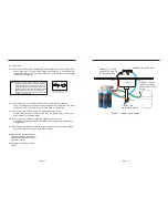
FIGURE 

22.

ACCESSORY DIAGRAM

FIGURE 

21.R.O. 

COMPONENTS DIAGRAM

5th  IN LINE POST CARTRIDGE

4 th MEMBRANE

FLOW RESTRICTOR

FAUCET

INSTALL KITS

BALL VALVE

WATER INLET

BALL VALVE FOR TANK

BOOSTER PUMP

SHUT OFF VALVE

1st CARTRIDGE

2nd CARTRIDGE

3 rd CARTRIDGE

Summary of Contents for ROQ-3405

Page 1: ...ments please make sure that power supply is removed and the water source is cut off 08 If the water pressure of installation area exceeds 80 psi please install pressure reducing valve 09 For this water purification equipment the ratio of produced pure water small molecule water for drinking and clean water large molecule water for use is around 45 55 10 For first time installation or filter elemen...

Page 2: ...ou can drink ready made water with pure and clean quality This is an innovation that breaks through traditional rules It integrates the effort of many senior engineers The product is developed through work of many years and large amount of research and development costs It has received many patents from many countries This equipment does not require pressurized water storage tank It will not cause...

Page 3: ...y situat ions that requ ire clean water Such as the following situat ion Make coff ee Make milk Make ice Blend juice Make tea Pet water use Cook spag het ti Cook soup Clean vege tabl e Make drink 1 4 Restriction on feeding water This filter is designed to be used with city water or underground water TDS less than 2000 PPM The feed water quality requirement is as follows Item Content Limits 1 Press...

Page 4: ...lectric cable attached with the machine is not enough 2 2 Machine installation Under sink The location of installation should be under the counter of kitchen Please make sure there is enough space to install the machine If depth of counter is small you may take off upper drop tray lower drop tray and antidust cover 2 2 1 If your counter material is made by concrete marble or other factors may not ...

Page 5: ...ue to length of faucet it will not be able to install Hole 1 Hole for installation of gooseneck faucet please select a position for the installation of gooseneck faucet Figure 14 Figure 10 Conventional faucet Figure 11 Figure 13 Figure 12 Hole2 Hole of water inlet provide power source through counter If the power source is under counter there is no need to drill a hole Hole 3 Hole for entrance of ...

Page 6: ...And the other side is connected to the ball valve of storage tank 2 4 5 Cutting a piece of100cm PE pipe and connect to the post in line cartridge and the other side is connected to inlet of faucet Please make sure all of above mentioned are OK and then manage the PE pipes then put it back to counter Any problem please call for service PE pipe quick connector Figure 16 Quick connecting pipe sketch ...

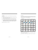
Page 7: ...ld water use calculation method calculated as 2 5 liters per person per day Types of filter cartridges outside appearance replacement time 1 replacement time 2 absorption capacity Results without replacement first stage sludge filter cartridge 1 micron meter external front installed filter cartridge 5 micron meter Second and third stage activated carbon filter cartridge 3 months 6 months 6 months ...

Page 8: ...el it s difficult to loosen the filter please try to knock the filter or turn on the gooseneck faucet to release the pressure Caution2 In order to avoid clogging on membrane please flush the system with pure water before replacing carbon filter Figure 19 Post in line activated carbon filter cartridge replacement diagram Take down first C clamp then push this adjustable clamp toward internal and th...

Page 9: ...ESSORY DIAGRAM FIGURE 21 R O COMPONENTS DIAGRAM 5th IN LINE POST CARTRIDGE 4 th MEMBRANE FLOW RESTRICTOR FAUCET INSTALL KITS BALL VALVE WATER INLET BALL VALVE FOR TANK BOOSTER PUMP SHUT OFF VALVE 1st CARTRIDGE 2nd CARTRIDGE 3 rd CARTRIDGE ...

Reviews: