background image

Pow’r Up Option

Page 24

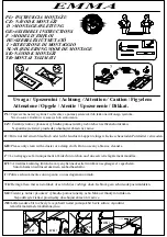
13 . Remove the bolt, plastic washer, metal 

washer, and nut from each side of the unit.

14 . With assistance, position the back in the slot 

on the seat as shown.

15 . Line up the holes and place the plastic 

washer between the back and the slot on the 

seat, insert bolt from the inside of the unit. Do 

the same on the other side.
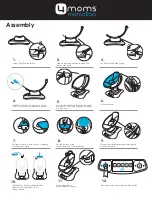
Assembly

Page 7

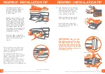
Charging the Battery

The EasyStand Bantam Medium Pow’r Up Lift uses two 12-volt sealed lead batteries rated at 2.9 amps 
each. An EasyStand Bantam Medium can be lifted approximately 100 times on one full battery charge. 
An audible alarm will sound when the battery is low. Please charge the battery after the alarm sounds. 
A battery needing to be fully recharged will take approximately 8 hours. The EasyStand Bantam 
Medium can be raised to the standing position while being charged. The function of the charger is to 
detect a full battery and then provide a constant potential power supply to hold the 
battery at a full condition without overcharging. When the battery EMF 
rises to a factory preset point, the charger circuit will not allow the peak 
output voltage to exceed that value. This factory setting protects a battery 
from excessive depletion of electrolyte, which can occur from overcharg-
ing. The charger can be found in the tool pouch on the back of the unit.

CAUTION: Use only the Linak charger, model number 10CH01S-00, 
provided by Altimate Medical with the Pow’r Up option.

1. Plug the receptacle into a wall outlet. The length of the charger cable 
is 80” (203cm). The light on the charger will be green indicating an open 
circuit.
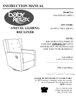
2. FIG . A- Plug the charger cord into the side of the hand control. The light 
on the charger will turn yellow indicating the batteries are being charged. 
The length of the hand pendant cable is 30” (76cm), retracted.
3. FIG . B- The unit will arrive unplugged from the battery, plug in the white 
cord that supplies power to the actuator and the black cord that supplies 
power to the remote. The black cord has a notch on it to orient the 
connector properly. Fully charge battery before use.
Note: The white cord has a rubber washer on it, which makes it very sticky 
and sometimes will not get pushed in completely, make sure to push the 
cord all the way into the battery.
4. When the batteries are charged, the light on the charger will turn green.
5. Fully charge the batteries every three months or less during periods of 
intermittent or non-use.

CAUTION: The Bantam Medium Pow’r Up Option is not designed for 
continuous use. Duty Cycle 5% Max, 1 min. / 19 min.

Raising the Lift - Press the UP (arrow up) button on the hand control to lift 
the seat.
           
Lowering the Lift - Press the DOWN (arrow down) button on the hand control to lower the seat.

CAUTION: Ensure the cables are attached properly per the instructions for use. Do not allow the cables 
to drag on the floor or to catch on objects.  

Pow’r Up Lift Option Usage

FIG . A

FIG . B

The hand pendant is a 

Type BF applied part.

Summary of Contents for Bantam Medium

Page 1: ...onitored by the attending therapist AMI maintains a policy of continual product improvement and reserves the right to change features specifications and prices without prior notification Check with AMI for latest info FORM MBANMAN 102218 REV D Copyright 2018 Altimate Medical Inc All rights reserved Printed in the U S A 262 West 1st St Morton MN 56270 USA Toll Free 800 342 8968 or 507 697 6393 Fax ...

Page 2: ...ate Medical s option ALTIMATE MEDICAL SOLE OBLIGATION AND YOUR EXCLUSIVE REMEDY UNDER THIS WARRANTY SHALL BE LIMITED TO SUCH REPAIR AND OR REPLACEMENT This warranty does not include any labor charges incurred in replacement parts installation Freight charges to factory are at the expense of consumer to seller Return freight charges will be prepaid by Altimate Medical For warranty service please co...

Page 3: ...nit The very close fit of its mating parts gives each pump its own break in feel and signature sound signaled by a squeaking or a less than smooth stroke If the pump is leaking oil or not holding properly contact your local EasyStand Supplier for a replacement Do not exert excessive force on the pump handle or use the pump handle to move an EasyStand This may cause damage to the pump handle and or...

Page 4: ...e listed in the product owner s manual can be made by the operator by following the instructions for use After an adjustment is made inspect the EasyStand to ensure all hardware and adjustable components are properly secured per the instructions for use Replacement of worn parts major adjustments or any other important corrections should be handled by an authorized supplier or service center Only ...

Page 5: ...n may be used to elevate the legrest with simultaneous recline of the backrest Ensure the necessary support and alignment options are in position prior to placing the user into the standing position If the unit was exposed to temperatures of less than 50 F 23 5 C the unit must warm to room temperature before use Operating Conditions Temperature 41 F 95 F 5 C 35 C Relative humidity 20 90 at 86 F 30...

Page 6: ... Bantam Medium can help prevent electromagnetic interference by maintaining a minimum distance between portable and mobile RF communications equipment trans mitters and the EasyStand Bantam Medium as recommended below according to the maximum output power of the communications equipment Rated maximum output power of transmitter 150 kHz to 80 MHz 80 MHz to 800 MHz 800 MHz to 2 5 GHz Separation dist...

Page 7: ... m Field strengths from fixed RF transmitters as deter mined by an electromagnetic site surveya should be less than the compliance level in each frequency range b Interference may occur in the vicinity of equipment marked with the following symbol IEC 60601 Test Level Electromagnetic Environment Guidance NOTE 1 At 80 MHz and 800 MHz the higher frequency range applies NOTE 2 These guidelines may no...

Page 8: ...e customer or the user of the EasyStand Bantam Medium should assure that it is used in such an environment Immunity Test Electrostatic Discharge ESD IEC 61000 4 2 6 kV contact 8 kV air 6 kV contact 8 kV air Floors should be wood concrete or ceramic tile If floors are covered with synthetic material the rela tive humidity should be at least 30 Mains power quality should be that of a typical com mer...

Page 9: ...e reached their end of life and need to be replaced do not open the control box please contact Altimate Medical Customer Service or your medical equipment dealer for information about purchasing a replacement control box It is recommended that the batteries be replaced every four years Please contact a local recycling authority for information about disposing of the old batteries IP Rating The IP ...

Page 10: ...el number 10CH01S 00 provided by Altimate Medical with the Pow r Up option 1 Plug the receptacle into a wall outlet The length of the charger cable is 80 203cm The light on the charger will be green indicating an open circuit 2 FIG A Plug the charger cord into the side of the hand control The light on the charger will turn yellow indicating the batteries are being charged The length of the hand pe...

Page 11: ...he back of the headrest and slide into desired posi tion tighten securely 26B To adjust the head support angle loosen the ratchet handle and place into desired position Tighten securely Foot plate Adjustment 27 Adjust the foot plate by loosening the red ratchet handle on the foot plate up or down and to the desired angle tighten securely Foot plates maybe be inverted for increased range Knee pad A...

Page 12: ...r additional positions vertically and horizontally The pads may also be bolted on at a straight 90º 180º or 270º position Please check for fit and interference by bringing the unit to the full standing position and back to sitting again without a user seated in the unit Due to the variety of adjustments that can be made the pads may not work properly in all settings or configurations Hip Support A...

Page 13: ... tighten securely 19 To adjust tray angle loosen one lever clamp approximately 2 turns at either side of the tray where the extension tubes are attached as shown Support the tray with one hand before fully loosening the second lever clamp 20 Adjust to desired angle and tighten securely Caution Extra care should be exercised if the tray is adjusted with a patient seated in the unit to ensure they a...

Page 14: ...cing the knob past its stop will damage the mechanism The tray may now be removed completely or adjusted to the desired position using the click detent positions as a guide 14 Release the gray plunger levers to re engage the locking plungers in the clamp knobs You may need to partially tighten the knobs and slightly move the tray back and forth to allow the locking pins to engage their home positi...

Page 15: ...controller is set in that position The foot bracket supports and back support are locked in relation to each other in Supine mode When in partial supine or full supine the user can be elevated to an upright position or descended to a reclined position If the unit is locked in supine mode you must only elevate the unit to the point where the footplate bracket comes perpendicular to the floor DO NOT...

Page 16: ...note that even though the controller is set to sit to stand mode the foot plate bracket must be brought perpendicular to the floor and locked into place If the bracket is not already in position this can be accomplished by pushing on the supine assist handle Listen for a clicking sound to indicate that the unit is locked into sit to stand mode If you can move the back support or foot supports forw...

Page 17: ... while the patient is seated the backrest will be 10 degrees BELOW parallel with the seat if the unit is placed in full supine For the comfort and safety of the patient the operator or attendant must be fully aware of back angle adjustment and should confirm same color settings on the seat depth and following arm BEFORE switching to Neutral or Supine modes Important All seat depth and following ar...

Page 18: ...tion Make sure to have one hand supporting the back assembly flipping the gray plunger lever will cause the back assembly to move freely 6 Using the back as a lever adjust the following arm so that the color of the seat depth decal matches the color in the indicator window on the following arm indicator window as shown Release the gray plunger lever to re engage the locking plungers in the clamp k...

Page 19: ...tion Make sure to have one hand supporting the back assembly flipping the gray plunger lever will cause the back assembly to move freely 6 Using the back as a lever adjust the following arm so that the color of the seat depth decal matches the color in the indicator window on the following arm indicator window as shown Release the gray plunger lever to re engage the locking plungers in the clamp k...

Page 20: ... while the patient is seated the backrest will be 10 degrees BELOW parallel with the seat if the unit is placed in full supine For the comfort and safety of the patient the operator or attendant must be fully aware of back angle adjustment and should confirm same color settings on the seat depth and following arm BEFORE switching to Neutral or Supine modes Important All seat depth and following ar...

Page 21: ...note that even though the controller is set to sit to stand mode the foot plate bracket must be brought perpendicular to the floor and locked into place If the bracket is not already in position this can be accomplished by pushing on the supine assist handle Listen for a clicking sound to indicate that the unit is locked into sit to stand mode If you can move the back support or foot supports forw...

Page 22: ...controller is set in that position The foot bracket supports and back support are locked in relation to each other in Supine mode When in partial supine or full supine the user can be elevated to an upright position or descended to a reclined position If the unit is locked in supine mode you must only elevate the unit to the point where the footplate bracket comes perpendicular to the floor DO NOT...

Page 23: ...cing the knob past its stop will damage the mechanism The tray may now be removed completely or adjusted to the desired position using the click detent positions as a guide 14 Release the gray plunger levers to re engage the locking plungers in the clamp knobs You may need to partially tighten the knobs and slightly move the tray back and forth to allow the locking pins to engage their home positi...

Page 24: ... tighten securely 19 To adjust tray angle loosen one lever clamp approximately 2 turns at either side of the tray where the extension tubes are attached as shown Support the tray with one hand before fully loosening the second lever clamp 20 Adjust to desired angle and tighten securely Caution Extra care should be exercised if the tray is adjusted with a patient seated in the unit to ensure they a...

Page 25: ...r additional positions vertically and horizontally The pads may also be bolted on at a straight 90º 180º or 270º position Please check for fit and interference by bringing the unit to the full standing position and back to sitting again without a user seated in the unit Due to the variety of adjustments that can be made the pads may not work properly in all settings or configurations Hip Support A...

Page 26: ...he back of the headrest and slide into desired posi tion tighten securely 26B To adjust the head support angle loosen the ratchet handle and place into desired position Tighten securely Foot plate Adjustment 27 Adjust the foot plate by loosening the red ratchet handle on the foot plate up or down and to the desired angle tighten securely Foot plates maybe be inverted for increased range Knee pad A...

Page 27: ...el number 10CH01S 00 provided by Altimate Medical with the Pow r Up option 1 Plug the receptacle into a wall outlet The length of the charger cable is 80 203cm The light on the charger will be green indicating an open circuit 2 FIG A Plug the charger cord into the side of the hand control The light on the charger will turn yellow indicating the batteries are being charged The length of the hand pe...

Page 28: ...e reached their end of life and need to be replaced do not open the control box please contact Altimate Medical Customer Service or your medical equipment dealer for information about purchasing a replacement control box It is recommended that the batteries be replaced every four years Please contact a local recycling authority for information about disposing of the old batteries IP Rating The IP ...

Page 29: ...e customer or the user of the EasyStand Bantam Medium should assure that it is used in such an environment Immunity Test Electrostatic Discharge ESD IEC 61000 4 2 6 kV contact 8 kV air 6 kV contact 8 kV air Floors should be wood concrete or ceramic tile If floors are covered with synthetic material the rela tive humidity should be at least 30 Mains power quality should be that of a typical com mer...

Page 30: ... m Field strengths from fixed RF transmitters as deter mined by an electromagnetic site surveya should be less than the compliance level in each frequency range b Interference may occur in the vicinity of equipment marked with the following symbol IEC 60601 Test Level Electromagnetic Environment Guidance NOTE 1 At 80 MHz and 800 MHz the higher frequency range applies NOTE 2 These guidelines may no...

Page 31: ... Bantam Medium can help prevent electromagnetic interference by maintaining a minimum distance between portable and mobile RF communications equipment trans mitters and the EasyStand Bantam Medium as recommended below according to the maximum output power of the communications equipment Rated maximum output power of transmitter 150 kHz to 80 MHz 80 MHz to 800 MHz 800 MHz to 2 5 GHz Separation dist...

Page 32: ...n may be used to elevate the legrest with simultaneous recline of the backrest Ensure the necessary support and alignment options are in position prior to placing the user into the standing position If the unit was exposed to temperatures of less than 50 F 23 5 C the unit must warm to room temperature before use Operating Conditions Temperature 41 F 95 F 5 C 35 C Relative humidity 20 90 at 86 F 30...

Page 33: ...e listed in the product owner s manual can be made by the operator by following the instructions for use After an adjustment is made inspect the EasyStand to ensure all hardware and adjustable components are properly secured per the instructions for use Replacement of worn parts major adjustments or any other important corrections should be handled by an authorized supplier or service center Only ...

Page 34: ...nit The very close fit of its mating parts gives each pump its own break in feel and signature sound signaled by a squeaking or a less than smooth stroke If the pump is leaking oil or not holding properly contact your local EasyStand Supplier for a replacement Do not exert excessive force on the pump handle or use the pump handle to move an EasyStand This may cause damage to the pump handle and or...

Page 35: ...ate Medical s option ALTIMATE MEDICAL SOLE OBLIGATION AND YOUR EXCLUSIVE REMEDY UNDER THIS WARRANTY SHALL BE LIMITED TO SUCH REPAIR AND OR REPLACEMENT This warranty does not include any labor charges incurred in replacement parts installation Freight charges to factory are at the expense of consumer to seller Return freight charges will be prepaid by Altimate Medical For warranty service please co...

Page 36: ...onitored by the attending therapist AMI maintains a policy of continual product improvement and reserves the right to change features specifications and prices without prior notification Check with AMI for latest info FORM MBANMAN 102218 REV D Copyright 2018 Altimate Medical Inc All rights reserved Printed in the U S A 262 West 1st St Morton MN 56270 USA Toll Free 800 342 8968 or 507 697 6393 Fax ...

Reviews: