


8
easyRAID S8A2-U4TT
Serial ATA Disk Array Systems
2
Bas
ic C
o
nfiguration –
Ins
talling Dis
ks
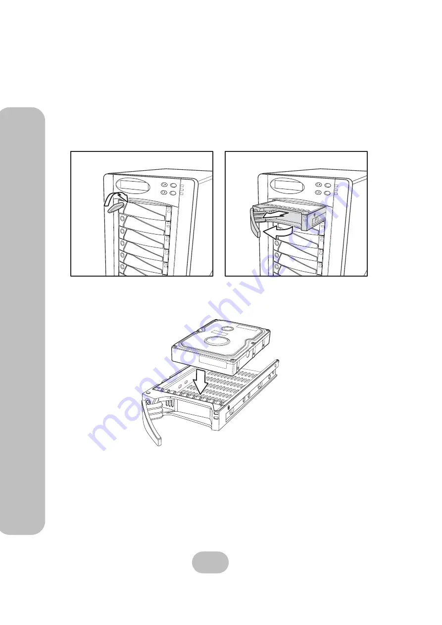
Installing Disks
This section describes how to install disks in the disk array system.
1
Unlock the disk tray
(A)
then pull the disk tray handle to the opened position
(B)
and
remove the disk tray
(C)
.
2
Insert the disk into the disk tray. The disk should face up with the connectors directed
toward the open rear of the tray.
3
Align the back of the disk with the back of the disk tray.
ESC
Enter
ESC
Enter
A
B
C
Summary of Contents for S8A2-U4TT
Page 2: ......
Page 4: ......
Page 6: ......
Page 32: ...22 easyRAID S8A2 U4TT Serial ATA Disk Array Systems 3 Maintenance Replacing a Fan ...