background image

Programmable Timer Features

•   Digital electronic time switch with daily programs

•   Repeat programs with 16 on/off settings and manual override

•   Lithium battery power reserve to keep time and programs even in power outage.

•  Auto time error corr/- 60 sec. weekly

Operation Instructions for Automatic Program Function

1.  Plug controller into 110 volt GFCI protected outlet. Red light on timer will come on to indicate 

power is being supplied to lights. After timer settings are made, the red light only comes on 

during operation of programmed Auto “On” setting or when ON in Manual mode (see Manual 

Mode section).

2. Remove clear plastic cover from timer. Be sure not to lose this cover.
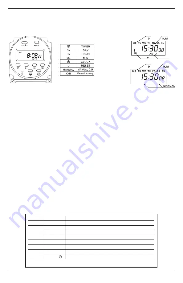
3.  Unlock the timer by pressing the “C/R” button four times. This removes the “a” character in 

lower left corner of the display screen. If no keys are selected in 15 seconds, the time will 

automatically lock. Or once programming is finished press “C/R” button to lock.

4.  To clear all programs, press the Reset button (labeled as 'c'). It is inset and will require a pen 

or small object to depress.

5.  Once unlocked, set the time by pressing the button with the clock icon, then use D+ to set 

the day of the week, H+ to set the hour (uses military time only) and M+ to set the minute. 

6. Up to 16 on/off settings can be programmed using the chart below.


Note:  Set times in sequence as you may not cross set. System will auto lock 

with no activity or data saved within 15 seconds.

Setting the Timer

Mount the weatherproof controller box in a secure location near a power supply 

and plug into 110 volt outlet. The controller is weatherproof and does not need 

to be protected from the weather.

PROGRAM

  Step 

Key 

Programming

  1 

Setting 1 ON time (display 1 on)

  2 

H+/M+ 

Setting hours and minutes to turn on

  3 

D+ 

Daily selects same time or separate times

  4 

Setting 1 OFF time (display 1 off)

  5 

H+/M+ 

Setting hours and minutes to turn off

  6 

D+ 

If using the same time everyday, do not press

  7 

Repeat 2-6  Set 2-16 ON/OFF time

  8 


End

If you do not require 16 settings, press clock icon to the end

ON

OFF

AUTO

Example

Program Functions

Example

Manual Functions

6

Summary of Contents for AquaShine RGB2

Page 1: ... codes Failure to follow manufacturer s installation instructions may result in electrical shock fire hazard personal injury or death damaged equipment provide unsatisfactory performance and will void manufacturer s warranty RGB2 RGB3 Thank you for purchasing the AquaShine color changing LED fountain light kit This kit will transform your fountain into a beautiful night time display These low volt...

Page 2: ...Two stainless steel mounting brackets with hardware One 2 x 1 splitter with waterproof connections for lights to power cord One outdoor rated controller transformer with digital timer and pigtail Stainless steel hardware packs LKH AFBW longer bolts for Aqua Fountain large washers and nylock nuts LKH KBW shorter bolts for 1 2 1 hp Kasco units Pan Head screws for 2 hp units washers and nylock nuts P...

Page 3: ...ils go around the motor screen in an orderly way so all lights can be connected without twisting Verify the o ring is present in the female portion of the connectors Figure 3 Push pigtails into splitter and secure with 1 2 turn quick connect nut on splitter Figure 4 6 Connect main cord to the remaining end of the splitter section Be sure the o ring is present Figure 3 and secure cords with 1 2 tur...

Page 4: ...s present in the female portion of the connectors Figure 3 Push pigtails into splitter and secure with 1 2 turn quick connect nut on splitter Figure 4 4 Connect main cord to the remaining end of the splitter section Be sure the o ring is present Figure 3 and secure cords with 1 2 turn quick connect nut Figure 4 Multiple cords can be connected up to 300 long between the light fixtures and the contr...

Page 5: ...d secure with 1 2 turn quick connect nut on splitter Figure 4 3 Connect main cord to the remaining end of the splitter section Be sure the o ring is present Figure 3 and secure cords with 1 2 turn quick connect nut Figure 4 Multiple cords can be connected up to 300 long between the light fixtures and the control unit 4 The main cord MUST BE SECURED to the float of the fountain Use plastic cable ti...

Page 6: ...r all programs press the Reset button labeled as c It is inset and will require a pen or small object to depress 5 Once unlocked set the time by pressing the button with the clock icon then use D to set the day of the week H to set the hour uses military time only and M to set the minute 6 Up to 16 on off settings can be programmed using the chart below Note Set times in sequence as you may not cr...

Page 7: ...Green Red off 10 Change Red Green Blue Yellow Green Purple Cyan Warm White 11 Change Demo Mode 12 Solid Red 13 Solid Green 14 Solid Blue 15 Solid Yellow Green 16 Solid Purple 17 Solid Cyan 18 Solid Warm White Operation Instructions for Manual Function 1 Be sure the controller is plugged into 110 volt GFCI protected outlet 2 Remove clear plastic cover from timer Keep cover safe and replace when fin...

Page 8: ... does not cover any cost associated with the installation or removal of the Product subject to a warranty claim All returned items will be inspected to determine cause of failure before a warranty claim is approved The exclusive remedies provided hereunder shall upon EasyPro s inspection and option be either repair or replacement of the Product or parts covered under this warranty Making a Claim A...

Reviews: