background image

EasyIO FG32 – Installation Guide v2.0 

14 


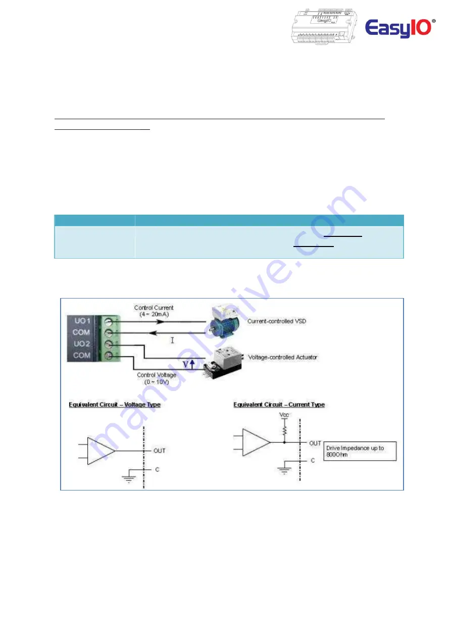
Universal Output Connection


EasyIO FG and FG+ Series has Universal Output connections. Each Universal Output can be configured to 
drive  voltage  or  current  output  or  digital  output  via  hardware  jumper  setting  and  internal  register 
settings.


**We DO NOT recommend you to drive a relay directly from UO 0-10V mode as it is not design for it 
and will damaged the UO.

 ** 


For current transmitter, the circuit able to drive load impedance up to 800 ohm which is ideal for long 
wire connection (up to 500 meter wire length).


For UO as digital output it can only support up to 24VDC and max load is 200mA each UO channel. AC 
power source is not allowed. It will damage the controller.


Universal Output


8 Channels (FG-32) , 6 Channels (FG-20)


Type


Current: 0 - 20mA, 4 - 20mA , max load impedance

 800 Ohm


Voltage: 0 – 10VDC , min load impedance 

1000 Ohm


Digital Mode; Max Sinking Current Rating: 

0.2A Max each channel


Universal Output Connection for Voltage and Current 


Summary of Contents for FG-32

Page 1: ...EasyIO FG32 Installation Guide v2 0 1 EasyIO FG Series and FG Series DDC User Reference ...

Page 2: ...4 th August 2013 Restore Factory settings 10 th Sept 2013 Added in wiring diagram 17 th August 2015 Updated LED indication table 17 th Jan 2018 Updated UO output specification 17 th Dec 2018 Remove Niagara Workbench Sedona files installation as N4 no longer supports Sedona framework Updated disclaimer and support channel emails addresses ...

Page 3: ...asyIO logo are registered trademarks of EasyIO Holdings Pte Ltd CPT Tool is by Online Tools Inc BACnet and ASHRAE are registered trademarks of American Society of Heating Refrigerating and Air Conditioning Engineers All other product names and services mentioned in this publication that are known to be trademarks registered trademarks or service marks are the property of their respective owners Co...

Page 4: ... receiving antenna Increase the separation between the equipment and receiver Connect the equipment into an outlet on a circuit different from that to which the receiver is connected Consult the dealer or an experienced radio TV technician for help Caution Any changes or modifications not expressly approved by the party responsible for compliance could void the user s authority to operate this equ...

Page 5: ... 7 Power supply Connection 7 RS485 Connection 8 Jumpers Setting 9 Wiring diagram 10 Digital Output Wiring Connection 11 Universal Input Connection 12 Universal Output Connection 14 Buttons and Indications 16 Login Details 17 Changing IP address 18 Restore factory settings 19 Technical Support 20 ...

Page 6: ...e and is encouraged for premium performance with Niagara Framework The Build in boot loader enable firmware upgrade to be carried out remotely No more manual service button needed is used Firmware upgrading now can be done remotely and without any assistant Document applies to both FG Series and FG Series both 20 points and 32 points hardware Comparison Chart below shows the difference between Eas...

Page 7: ...connection use individual power supply for each controller If a single power supply is used make sure controller power supplies are connected with the same polarity Electrical Power Supply 24V AC 5 or 24V DC 20 15 Consumption 750 mA Operating Temperature 32 to 150 Deg F 0 to 65 Deg C Storage Temperature 4 to 150 Deg F 20 to 65 Deg C Operating Humidity 10 to 95 relative humidity non condensing Powe...

Page 8: ...an be avoided keep it as short as possible and never connect more than one device to the wire branch it is not recommended Be careful if single power supply is used for all connected RS485 device make sure all devices are having the same ground connection Make sure you are connecting the same wire for the same terminal position all H terminals connected to the same wire Physical Interface 1 and EI...

Page 9: ...EasyIO FG32 Installation Guide v2 0 9 Jumpers Setting Below image shows the jumper setting for Universal Input Universal Output Watchdog and also EIA 485 120 Ohm terminations ...

Page 10: ...EasyIO FG32 Installation Guide v2 0 10 Wiring diagram ...

Page 11: ... general purpose isolated digital output connections relay output Pilot Duty rating is as below Pilot Duty 24 VAC 2 0A 24 VDC 2 0A Digital Output 8 Channels FG 32 2 Channels FG 20 Type Relay Contacts SPST NO 48VA at 24VAC It does not output voltage or current It is a dry relay contact Digital Output Connection ...

Page 12: ...Shunt 1K Balco 1K Platinum All 0 01 Deg C UI as Digital Input Voltage Free Contact a Resistance The working range of resistance is 500 Ohms 500K Ohms The commonly used Thermistor like 10K 10K with Shunt 1K Balco and 1K Platinum are all supported b Voltage Two selection of working range 0 5V and 0 10V The minimum input impedance of voltage input is 1 Mega Ohm c Current Two selection of working rang...

Page 13: ...EasyIO FG32 Installation Guide v2 0 13 Universal Input as Pulse Input specifications Max 20Hzat 50 cycle ...

Page 14: ... damaged the UO For current transmitter the circuit able to drive load impedance up to 800 ohm which is ideal for long wire connection up to 500 meter wire length For UO as digital output it can only support up to 24VDC and max load is 200mA each UO channel AC power source is not allowed It will damage the controller Universal Output 8 Channels FG 32 6 Channels FG 20 Type Current 0 20mA 4 20mA max...

Page 15: ...x load for Universal Output as Digital Output is 200mA each channel Refer below table for software configurations of UO as DO A Digital Output Block must be used EasyIO FG32 FG32 Physical Universal Output Digital Output Block Channel UO1 DO 9 UO2 DO 10 UO3 DO 11 UO4 DO 12 UO5 DO 13 UO6 DO 14 UO7 DO15 UO8 DO 16 EasyIO FG20 FG20 Physical Universal Output Digital Output Block Channel UO1 DO 9 UO2 DO ...

Page 16: ...d to activate the built in boot loader program for software upgrade Each digital output has a correspondence LED to indicate its current state Image shows the Reset button Service button and also TXRX indicators Image shown is an EasyIO FG 32 unit Image shows the Status indicator Error indicator and individual Digital Output indicator Button and LED indications Image shown is an EasyIO FG 32 unit ...

Page 17: ...ing on the Communication port TXRX is used to indicate when there are 4 TX2 RX2 Communication activities in Port 2 Transmitting or Receiving on the Communication port Login Details EasyIO FG and FG Series details are as below Sedona Login Username admin Password no password FTP client Webuser Login This login allows user to edit the web files or view CPT graphics deployment files Username webuser ...

Page 18: ...he object IP under the Service folder Step 2 Click IP object and view properties at the side bar At the newIpAddress newSubnetMask and newGateway property enter your new IP address Inserting invalid values to these properties will brick the network settings A restore factory default is required if controller unable to connect currentDhcp and newDhcp property only supported by FS Series controllers...

Page 19: ...2 168 10 11 2 Clear the Sedona application in the Sedona VM back to default default app is an empty app 3 Default Sedona apps default login is admin no password Step 1 Make sure you backup the Sedona apps if you have connection to the EasyIO FG32 Step 2 Cycle power or toggle the reset button Within 5 seconds press and HOLD down the service button until the Error LED starts to flash approximately 2...

Page 20: ...n Guide v2 0 20 Technical Support For technical issue please contact respective region support channel Worldwide and Asia Pacific Support support easyio com Americas Support support easyio pro Europe Support support easyio eu ...

Reviews: