


To order parts and supplies: 800.343.9353 >> eastwood.com
13
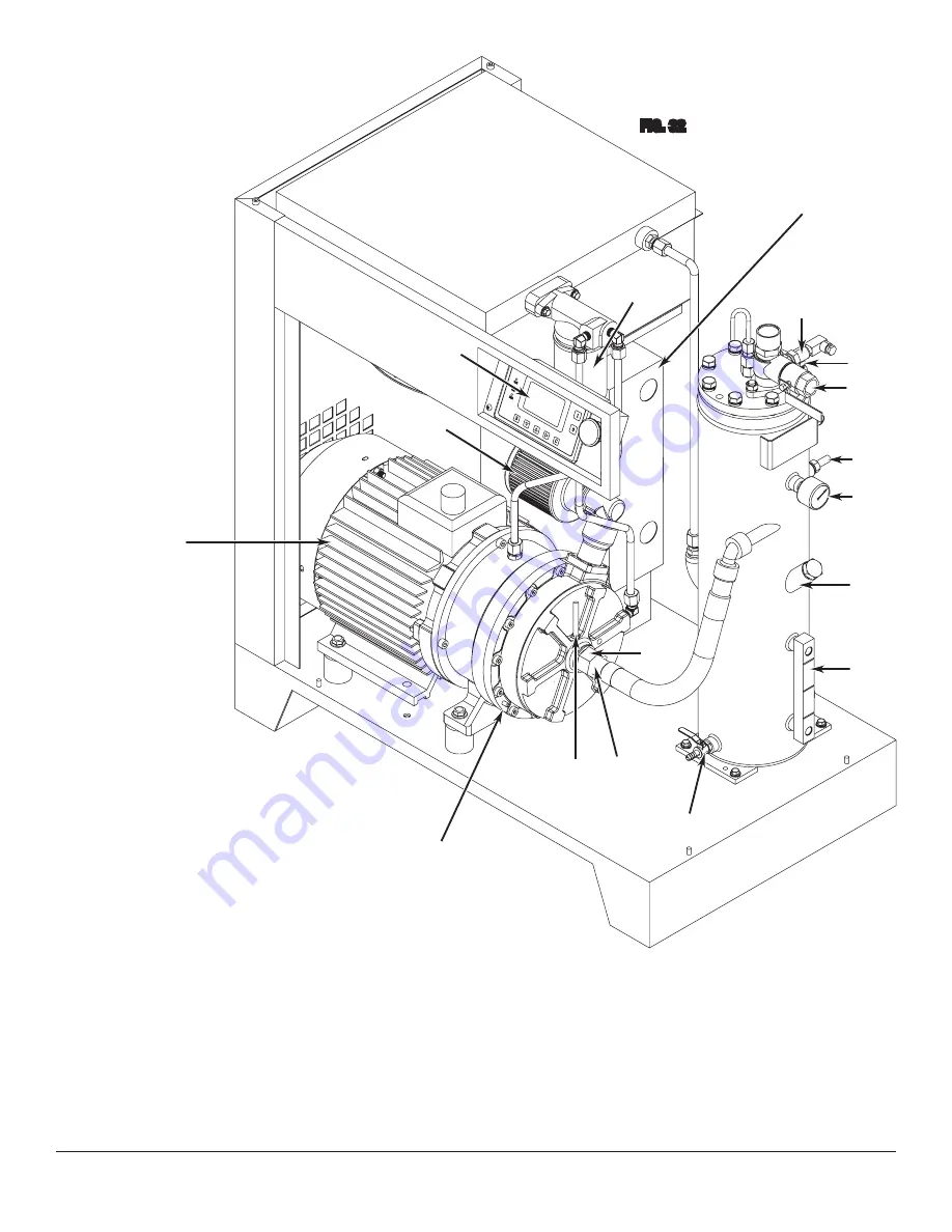
SCROLL COMPRESSOR
COMPONENT
IDENTIFICATION
(FIG 32)
AA
– Motor
BB
– Scroll
CC
– Scroll Compressed Air Outlet
DD
– Scroll Output Air Temperature Sensor
EE
– Oil and Air Separator/Oil Reservoir
FF
– Oil Drain Valve
GG
– Oil Level Sight Gauge
HH
– Oil Fill Port
JJ
– Air Pressure Gauge
KK
– Oil Temperature Sensor
LL
– Pressure Safety Release Valve
MM
– Pressure Sensor
NN
– Compressed Air Outlet Port
PP
– Pressure Switch
– Oil Heat Exchanger
RR
– Oil Filter
SS
– Microprocessor Control Panel
TT
– Electrical Cabinet
UU
– Air Inlet/ Air Filter Housing
FIG. 32
AA
BB
CC
DD
EE
FF
GG
HH
KK
LL
MM
NN
PP
RR
SS
TT
UU
✓
✓
✓
✓
✓
✓
✓
✓
✓
✓
✓
✓
✓
✓
✓
✓
JJ
✓