10
Eastwood Technical Assistance: 800.544.5118 >> [email protected]
To order parts and supplies: 800.345.1178 >> eastwood.com
7
TO BEGIN ABRASIVE BLASTING
IMPORTANT NOTES:
Start with all valves in the closed position.
Following the instructions below will help prevent the
formation of clogs in the Outlet Manifold, Abrasive Hose
the Safety Trigger and Nozzle.
Please note that as a result of many influencing variables
such as the available compressed air supply CFM and
pressure as well as the weight, density and grit size of the
selected media combined with atmospheric pressure and
humidity will all greatly affect the Blaster valve settings.
The set-up process requires some repeated “trial and
error” while following step 8 to achieve the best blaster
performance.
1.
Connect air compressor to the Inlet Connector.
2.
Open Air Supply Valve fully.
3.
Open Throttling Valve to approx. 1/2 way.
4.
Check for leaks at the Filler Cap and along all hoses
and fittings as the system pressurizes. If leaks are
observed, release the pressure from the tank and
repair immediately.
5.
Point Safety Trigger Nozzle in a safe direction away
from people, pets or anything around you that may
be harmed by direct or indirect high-pressure
abrasive stream.
6.
Press and hold Safety Trigger until air is flowing
through the Nozzle.
7.
While holding the Safety Trigger open, slowly open the Abrasive Control Valve until abrasive material begins to flow out of the
Safety Trigger Nozzle. Do not open Abrasive Control Valve any further at this point but follow procedure below.
8.
Abrasive Flow Adjustment as follows:
IMPORTANT NOTE:
The Abrasive Flow is a finely tuned combination of two adjustments (Throttling Valve and Abrasive
Control Valve) which will vary widely with different media, air supply and atmospheric conditions.
It is necessary to follow this “tuning” procedure at the beginning of every blasting job.
NOTE:
Operating the blaster with all valves wide open will result in decreased performance and effectiveness.
Too much air flow/not enough media will result in a high velocity but ineffective stream.
Too much media/not enough air flow will result in a soft, weak blast stream.
a.
Adjust air pressure with the Throttling Valve. The Throttling Valve controls the velocity of material flow.
b.
Adjust abrasive flow with Abrasive Control Valve. The Abrasive Control Valve controls the amount of abrasive introduced
into the stream.
c.
Increase Throttling Valve first in small increments followed by the Abrasive Control Valve second until an ideal smooth,
forceful flow is achieved.
d.
The above steps may need to be repeated in sequence until an ideal balance can be reached.
9.
Begin blasting.
10.
Drain moisture trap frequently during use. Do not allow moisture to fill more than 1/2 the water trap bowl. Do not leave water
standing in moisture trap when done blasting.
ASSEMBLY
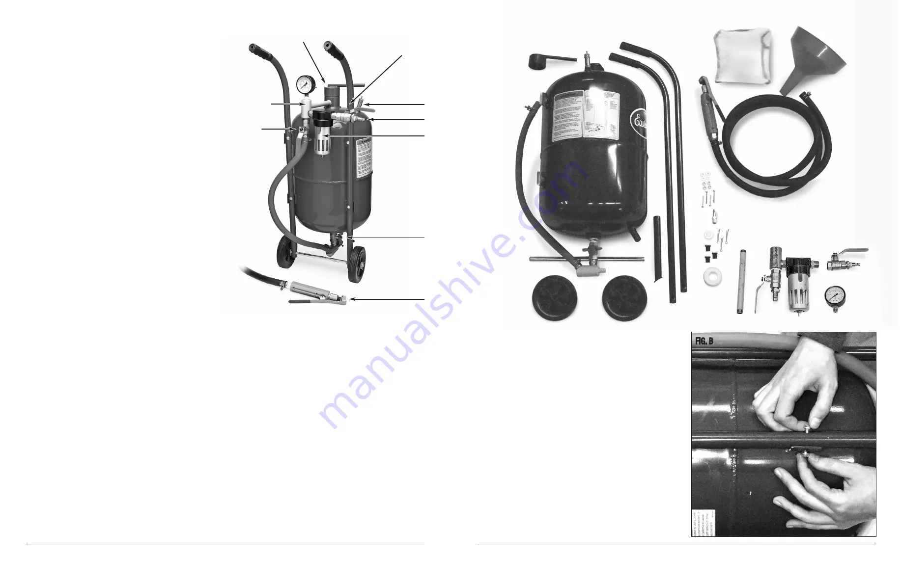
1.
Remove parts from container and verify that all components
are present
(Fig A)
.
2.
Place Tank Assembly on a soft work surface for assembly with
the welded-on Handle Bar mounting tabs facing upward
(Fig B)
.
3.
Place left and right tubular Handle Bars (
NOTE:
2 pieces on
Item #’s 51117 & 51118. One piece Handle on #51119) over
the welded-on Handle Bar mounting tabs. The curved ends with
rubber hand grips should point upward and be oriented toward
the top of the Tank Assembly
(Fig B)
.
4.
Attach the left and right tubular Handle Bars to the 4 outward
curved mounting tank mounting tabs with 4 supplied 1-3/8” long
Phillips head screws and nuts. Note: Place screws through holes
with nuts and washers facing forward to avoid possible future
injury
(Fig B)
.
5.
Slide Axle through 2 holes in lower ends of tubular Handle Bars.
FIG. A
FIG. B
Filler Cap
✓
Inlet Manifold Assembly
Throttling Valve
Air Supply Valve
Pressure Relief Valve
Air Inlet
Moisture Trap
Abrasive Control Valve
Blast Hose and
Safety Valve Assembly
✓
✓
✓
✓
✓
✓
✓
✓


