background image

2


Eastwood Technical Assistance: 800.343.9353  >>  [email protected]

The 

EASTWOOD 7” X 12” MINI LATHE

 is equipped with all the features found on large lathes in a compact, home workshop-friendly size. Auto-feed and  

selectable gear train components allow complex threading operations with a high degree of precision. The included inside and outside 3-Jaw Chuck set will  
accommodate a wide range of workpiece configurations for most turning and cutting operations.

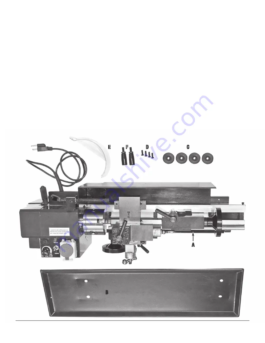
CONTENTS

PARTS

(1)

 Main Lathe Unit with 3-Jaw Chuck (installed) 

[A]

(1)

 Chip Tray 

[B]

(4)

 Rubber Mounting Feet 

[C]

(4)

  M6 Pan Head Mounting Screws 

[D]

(1)

  Clear Plastic Chuck Guard 

[E]

(2 

Handwheel Crank Handles 

[F]

SPECIFICATIONS

Power Requirements:


120 VAC, 60hz.

Maximum Tool Size:


5/16” x 5/16” [8mm x 8mm]

Compound Travel:


2.75” [69.8mm]

Headstock Spindle Size:


3” [76.2mm]

Headstock Spindle Bore:


0.78” [19.8mm]

Swing Over Bed:


7” [177.8mm]

Distance Between Centers:


12” [304.8mm]

Headstock Spindle Taper:


Morse Taper 3

Spindle Speed Range:


0-2500 RPM

Spindle Bearings:


Sealed and Permanently Lubricated

Tailstock Spindle Quill Travel:

  2.5” [63.5mm]

Tailstock Taper:


Morse Taper 2

Compound Slide Graduations:

 0.001”

B

A

E             F                D                                  C

Summary of Contents for 32497

Page 1: ...7 X 12 MINI LATHE INSTRUCTIONS Item 32497 ...

Page 2: ...PARTS 1 Main Lathe Unit with 3 Jaw Chuck installed A 1 Chip Tray B 4 Rubber Mounting Feet C 4 M6 Pan Head Mounting Screws D 1 Clear Plastic Chuck Guard E 2 Handwheel Crank Handles F SPECIFICATIONS Power Requirements 120 VAC 60hz Maximum Tool Size 5 16 x 5 16 8mm x 8mm Compound Travel 2 75 69 8mm Headstock Spindle Size 3 76 2mm Headstock Spindle Bore 0 78 19 8mm Swing Over Bed 7 177 8mm Distance Be...

Page 3: ...M 1 2 Pc HSS Cutter Set N 1 Tool Holder O 1 Spare Fuse P 1 Oil Dispenser Q 1 30 Tooth Plastic Gear R 1 35 Tooth Plastic Gear S 2 40 Tooth Plastic Gears T 1 45 Tooth Plastic Gear U 1 50 Tooth Plastic Gear V 1 55 Tooth Plastic Gear W 1 57 Tooth Plastic Gear X 1 60 Tooth Plastic Gear Y 1 65 Tooth Plastic Gear Z Q P H N O X Y Z W V U R S T J K G L M LEARN HOW TO SET UP AND USE YOUR LATHE with FREE Ins...

Page 4: ...ing sharp metal INJURY HAZARD This tool can quickly start up while connected to an electrical supply causing serious personal injury Always disconnect the Lathe from the electrical supply before making adjustments changing tooling or performing maintenance EYE INJURY HAZARD The cutting process ejects chips at high velocity Always wear ANSI approved eye protection when operating this equipment INJU...

Page 5: ...s or moving parts Damaged or entangled cords increase the risk of electric shock e When operating electrical equipment outdoors use an extension cord suitable for outdoor use Use of a cord suitable for outdoor use reduces the risk of electric shock 3 PERSONAL SAFETY a Stay alert watch what you are doing and use common sense when operating electrical equipment Do not use electrical equipment while ...

Page 6: ...s are less likely to bind and are easier to control g Use the electrical equipment accessories and tool bits etc in accordance with these instructions and in the manner intended for the particular type of electrical equipment taking into account the working conditions and the work to be performed Use of the electrical equipment for operations different from those intended could result in a hazardo...

Page 7: ...w Bearing 13 Compound Slide Feed Handle 14 Thread Dial Indicator 15 Automatic Feed Lever 16 Cross Slide Feed Handle 17 Apron 18 Manual Saddle Feed Handle 19 Leadscrew 20 Motor Brush Cap 21 Thread Dial indicator Chart 22 Running Gear Cover 23 Variable Speed Control Knob 24 Forward Off Reverse Switch 25 Emergency Stop Switch 26 High Low Speed Range Lever 27 Leadscrew Forward Neutral Reverse Lever 1 ...

Page 8: ...ion by a single Locking Nut 10 at its base The Tailstock Spindle 8 is designed with an internal No 2 Morse Taper for use with the included Morse Taper No 2 Dead Center L THE SADDLE The Saddle carries the Cross Slide 6 on to which is mounted the Compound Slide 7 with the Tool Post 5 allowing intricate and delicate operations to be performed It may be driven by the Leadscrew via a Drive Nut to provi...

Page 9: ...one edge When attached that edge is biased toward the rear of the Main Lathe Unit Insert an M6 Pan Head Screw D through the recess in each of the four Rubber Mounting Feet C Align the holes in the Chip Tray with the tapped holes in the Lathe Base then insert and thread the M6 Screws into the tapped holes Tighten the four screws securely then rotate the Assembly to an upright position resting on th...

Page 10: ...d 18 however the Crank Handles F are left uninstalled to prevent damage To install Thread the exposed threaded post of the Crank Handle F into the tapped hole of the Handwheel using a screwdriver in the slot on the outer end FIG 9 When fully threaded in tighten the locknut to secure in place Verify that the Handle freely rotates Saddle cross slide and compound slide adjustments are all factory set...

Page 11: ...t the FORWARD OFF REVERSE Switch C to the OFF position for 5 seconds FIG 10 If at any time the Amber LED is illuminated this indicates a Fault condition and the Lathe will not run Potential Fault causes are The Lathe was overloaded The Lathe was stopped by depressing the Emergency Stop Button The Plastic Chuck Guard was lifted while the Lathe was running NEVER attempt to switch from FORWARD to REV...

Page 12: ...OFF REVERSE Switch to OFF then unplug the Power Cord The Automatic Feed must always be intentionally selected and the operator MUST be aware of this choice If Automatic Feed is selected the Leadscrew Forward Neutral Reverse Lever 27 FIG 2 should be set to FORWARD If Automatic Feed is not selected the Leadscrew Forward Neutral Reverse Lever 27 should be set to NEUTRAL To do this Firmly grasp the Kn...

Page 13: ...Cross Slide so that the tool touches the surface of the work While making these adjustments rotate the Chuck by hand to prevent anything from contacting it when turning takes place and that there is adequate clearance between the Saddle Cross Slide Tool Post or cutting tool and the Chuck It may be necessary to adjust the position of the Compound Slide or reposition the work in the Chuck to guarant...

Page 14: ... mark on the surface denoting the end of cut pull the Auto Lever UP sharply and ensure it stays UP If a degree of accuracy is required it is recommended that you finish the cut by hand NOTE If a shoulder with perfectly clean corners is required then an appropriately shaped tool must be used 4 Retract the tool one or two complete turns on the cross slide feed then wind the saddle so that the tool i...

Page 15: ... gears for the thread required and correctly mount the cutting tool Set the required depth of cut and position the tool ready to begin cutting NOTE Depth of cut is vitally important and may be calculated or obtained from an appropriate reference manual 2 Take all necessary precautions previously stated and start the machine with the Automatic Feed Lever in its disengaged position UP 3 Engage the A...

Page 16: ...various types of material etc and it is strongly advised that you consult appropriate handbooks or seek advice from a qualified person The chart below shows the thread sizes that may be cut using the gear configuration shown in the corresponding columns NOTE The factory default setup for the lathe provides for normal turning using the power or auto feed and the gear configuration is as follows Gea...

Page 17: ...60T 57T 20 40T 50T 22 40T 55T 24 40T 60T 26 40T 65T 28 20T 35T 32 20T 40T 36 20T 45T 38 20T 50T 50T 57T 40 20T 50T 44 20T 55T 48 20T 60T 52 20T 65T GEAR SELECTION CHART FOR CUTTING METRIC THREADS mm PITCH GEAR A B C D 0 4 20T 50T 40T 60T 0 5 20T 50T 60T 0 6 40T 50T 30T 60T 0 7 40T 50T 35T 60T 0 8 40T 50T 40T 60T 1 0 20T 60T 30T 1 25 50T 40T 60T 1 5 40T 60T 40T 1 75 35T 60T 30T 2 0 40T 60T 30T ...

Page 18: ...tely and provide easier re assembly loosen and remove the nut retaining the Shaft carrying Gears B and C and the nut retaining the Adjuster A FIG 18 3 Carefully remove the Gears taking care not to dislodge the small Keys on each shaft 4 Install the Gears as determined by the requirements of the desired screw thread NOTE The number of teeth is clearly molded in the face of each gear 5 Replace the r...

Page 19: ...ch and re tighten locknuts without moving the Gib Screws 7 Test once again and repeat steps 4 and 5 or 6 if required 8 When adjustments are completed retract the Slide fully and apply a light machine oil to all mating surfaces and the Feed Screw thread then wind the Slide back to the normal position CROSS SLIDE FEED HANDLE The Cross Slide Feed should operate smoothly and the Scale must rotate with...

Page 20: ...8 1 to 8 52 1 3 5 7 USING THE THREAD DIAL INDICATOR Mounted on the Base adjacent to the Auto Feed Lever is the Thread Dial Indictor FIG 22 This is directly connected to the as the Leadscrew turns the Dial rotates Eight radial markings are etched into the Dial face and are used to determine the exact position of the Leadscrew thread in relation to the Saddle The numbers on the SCALE column of the T...

Page 21: ...ly Disengage the Auto Feed Lever as the Cutting Tool approaches the end of the thread NOTE Engaging the Auto Feed Lever on the same exact number on the Dial Indicator while it passes the etched reference mark on the Dial Indicator Housing will guarantee that the Half Nuts of the Auto Feed mechanism engage on the same thread on the Leadscrew every time on every pass which produces a perfect thread ...

Page 22: ...e the Gear Train Cover to access the left side Leadscrew bearing 6 Add a few drops of a good quality medium bodied machine oil to all sliding rotating and pivoting points Lubricate the Compound Slide Oilway located on the top surface of the Bed adjacent to the guide rail FIG 25 AFTER EACH USE 1 Carefully remove all swarf and metal chips from the Lathe 2 If coolant has been used make sure it is all...

Page 23: ...plan work to accommodate limits of machine Too fast of a feed rate Slower feed rate Motor Overheating Motor overloaded Reduce workload on motor Workpiece too large for size of lathe Re plan work to accommodate limits of machine Too aggressive deep of cut being attempted Re plan work to accommodate limits of machine Too fast of a feed rate Slower feed rate Excessive or Unusual Lathe Vibration and N...

Page 24: ...described in this manual Worn or incorrect Tool profile Sharpen Tool or select better profile Too much play in the Gibs Adjust Gibs per procedure described in this manual Tool mounted too high or above center Adjust Tool below center Cross Slide Compound Slide or Car riage Feed loose or sloppy Too much play in the Gibs Adjust Gibs per procedure described in this manual Handwheel loose Tighten Hand...

Reviews: