

To order parts and supplies: 800.343.9353 >> eastwood.com
11
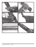
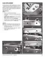
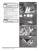
- Pull the Actuating Lever/Sector Gear from the assembly.
- Remove the left side Snap Ring securing the left Pivot Arm to the
Main Shaft
(FIG 29)
. then move the Main Shaft back slightly then
Very Carefully lower the left Pivot Arm
(FIG 30)
.
- Pull the Main Shaft from the right side of the Main Frame all to-
gether with the right Pivot Arm and the Actuating Lever/Sector Gear
still attached.
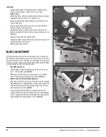
- Remove the Fixed Plate and Rack Assembly using an 18mm wrench
and 10mm hex key.
- Remove the Moving Shear Blade with an 18mm wrench
(FIG 31)
.
- The V-Upper Blade can now be removed from the back side of the
Moving Shear Blade, using a 16mm wrench.
- The Fixed Blades are now fully exposed and may be removed with
a 16mm wrench
(FIG 32)
.
Take note of the position of the Actuating Lever/Sec-
tor Gear position and relation to the teeth with those
of the Rack for re-assembly.
Blades have sharp edges. Use extreme caution and
wear heavy gloves when handling.
FIG. 29
FIG. 30
FIG. 31
FIG. 32
Left Pivot Arm
Moving
Shear Blade
Left Pivot Arm
✓
Main
Shaft
Drive
Plate
✓
✓
Fixed Blade
✓
✓
Adjustable
Down Blade
Shown with
Moving Shear Blade removed


