background image


User’s Manual


48 

LAX Series DVR 


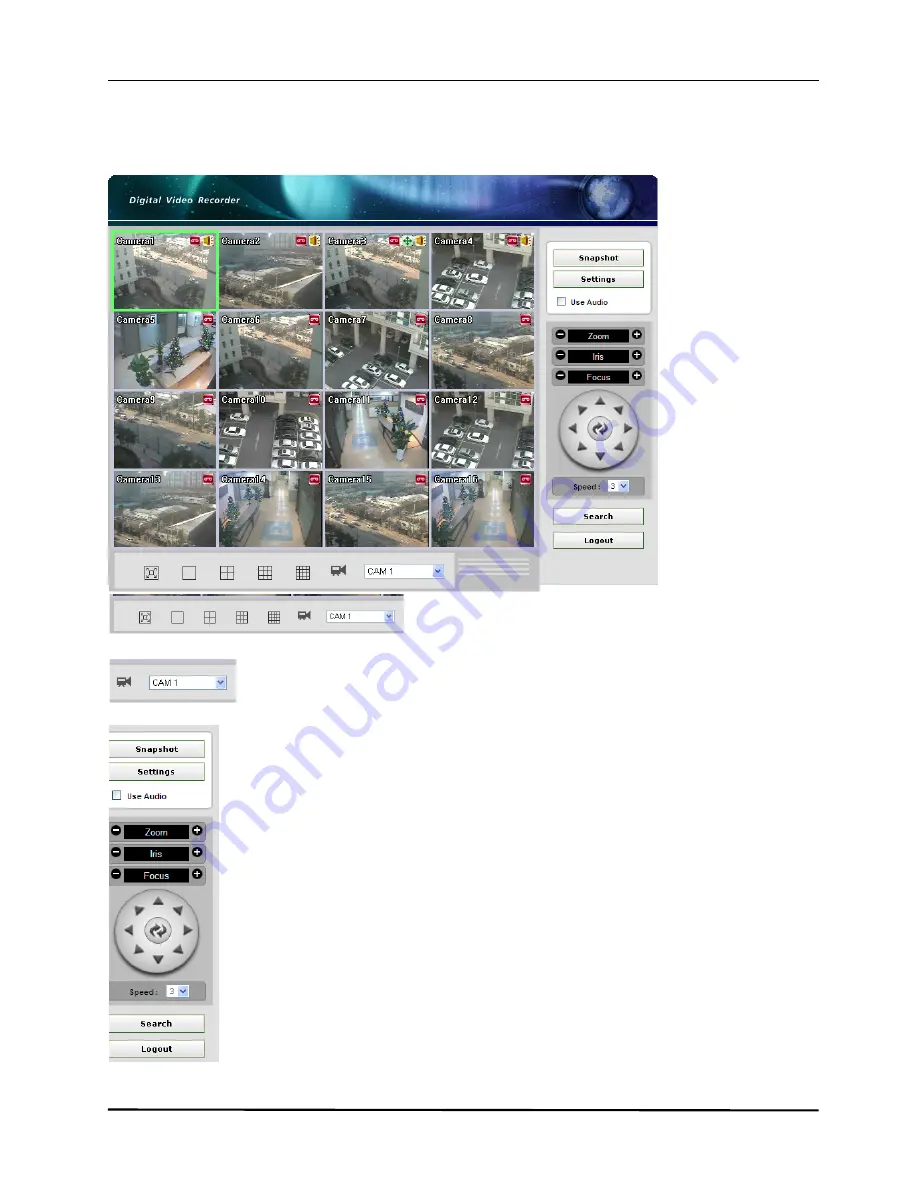
3.2. Live Mode 


                                                            :

 Select a display mode.   

(Full Screen Display / 1 / 4 / 9 / 16 CH Display) 

: Select a camera to display or control. 


Snapshot:

 Click to take a snapshot from the live screen.


Settings:

 Click to set DVR configuration. 

Use Audio:

 Click to enable or disable live audio. 

Zoom:

 Zoom in, Zoom out 

Iris:

 Control iris 

Focus:

 Focus in, Focus out 


Pan/Tilt Control 


Speed:

 set the speed of PTZ control 

Search:

 Click to load search mode 

Logout:

 Click to logout of WEB DVR 


Summary of Contents for LAX 1612

Page 1: ...Standalone DVR LAX Series H 264 DVR USER S MANUAL LAX 912 LAX 1612 ...

Page 2: ...ations 11 CHAPTER 2 MAIN SYSTEM APPLICATION 12 2 1 Startup Screen 13 2 2 Login 14 2 3 Exit Log Out 15 2 4 Panel Menu 16 2 5 System Configuration 17 2 6 Camera Configuration 22 2 7 Event Configuration 28 2 8 Network Configuration 33 2 9 Information Configuration 38 2 10 Search Features 42 CHAPTER 3 WEB DVR 46 3 1 Login 47 3 2 Live Mode 48 3 3 Search Mode 49 3 4 Setting Mode 50 WARRANTY 55 ...

Page 3: ...User s Manual 2 LAX Series DVR CHAPTER 1 INTRODUCTION 1 1 Contents 3 1 2 Installation Guide 4 1 3 Part Name 4CH 6 1 4 Part Name 9CH 16CH 8 1 5 Specifications 11 ...

Page 4: ... s Manual MOUSE REMOTE CONTROLLER Contents are subject to change without notice INTRODUCTION 1 1 Contents CAUTION Danger of explosion if battery is incorrectly replaced Replace only with the same or equivalent type LAX 412 4 Ch DVR LAX 912 1612 9 16Ch DVR ...

Page 5: ...prevent from overheating do not block cover or ventilation SHOCK Place the product where can be free from outer physical shock HUMIDITY Do not place a humidifier near the product as extreme humidity can badly affect the product s normal operation TEMPERATURE Avoid dust humidity and do not place the product where temperature changes extremely ELECTRIC NOISE ...

Page 6: ...al noise due to radio frequency DIRECT RAY OF LIGHT Direct ray of light can cause abnormal operation Keep the product away from direct ray of light VIBRATION Install the product on even place where no vibration INSTALLATION The socket outlet shall be installed near the apparatus and shall be easily accessible ...

Page 7: ...he power is on NETWORK LED The LED is on when network is in active HDD LED The LED is on when HDD is in active USB USB Flash drive can be connected to backup and firmware upgrade Notice Mouse connection is not available on Front USB Rear Panel LAN MOUSE VGA VIDEO INPUT SPOT OUTPUT MONITOR OUTPUT AUDIO OUTPUT AUDIO INPUT RS485 SENSOR INPUT RELAY OUTPUT POWER INPUT ...

Page 8: ...s Manual 7 LAX Series DVR Remote Controller 4CH POWER BUTTON MUTE BUTTON MENU BUTTON CANCEL BUTTON LIVE MODE BUTTON SEARCH MODE BUTTON CONFIGURATION CONTROL BUTTON PLAYBACK CONTROL BUTTON BACKUP MENU BUTTON ...

Page 9: ...Z Control screen Force Recording Change recording mode to force recording mode Change setting by full frame on all channels PLAYBACK BUTTONS Used for operation in playback mode MENU BUTTON Used to enter menu mode CANCEL BUTTON Used to cancel and exit BUTTONS Used to control PTZ zoom in out of time bar and change configurations AUTO OK BUTTONS Used to control change configuration USB USB storage de...

Page 10: ...User s Manual 9 LAX Series DVR 16CH POWER VIDEO INPUT VIDEO LOOP OUTPUT MULTIPLEX OUTPUT SPOT OUTPUT AUDIO INPUT 4 CHANNEL AUDIO OUTPUT LAN RS232 VGA SENSOR INPUT RS485 RELAY OUTPUT ...

Page 11: ... FORCE RECORDING BUTTON ZOOM IN CHANGE BUTTON ZOOM OUT CHANGE BUTTON MENU BUTTON CANCEL BUTTON LIVE MODE BUTTON SEARCH MODE BUTTON CONFIGURATION CONTROL BUTTON PLAYBACK CONTROL BUTTON PTZ CONTAROL BUTTON SPLIT SCREEN MODE BUTTON SWITCH SCREEN MODE BUTTON BACKUP MENU BUTTON ...

Page 12: ...Input Output RCA cable 1 line 1 line 4 line 1 line Sensor Input Relay Output 4 line 1 line 8 line 4 line 16 line 4 line Display Mode 1 4 and sequential PIP 1 4 9 and Sequential PIP 1 4 9 16 and Sequential PIP Backup Media USB Flash Drive Network Backup USB Flash Drive DVD W Option Network Backup Storage Media Max 1 HDD Front 1 USB Max 3 HDDs 1 USB memory Recording Mode Method Motion detection and ...

Page 13: ... APPLICATION 2 1 Startup Screen 13 2 2 Login 14 2 3 Exit Log Out 15 2 4 Panel Menu 16 2 5 System Configuration 16 2 6 Camera Configuration 22 2 7 Event Configuration 28 2 8 Network Configuration 33 2 9 Information Configuration 37 2 10 Search Features 41 ...

Page 14: ... on front panel or power button on remote controller As DVR starts the system will detect NTSC PAL automatically In a few seconds live images would be displayed The above screen will appear as DVR system starts when booting is finished This may take up to 1 minute to check the system status ...

Page 15: ...e required You will see the numeric buttons to select 3 Click to execute HR04 system To specify password to users certain configurations are required Menu System Password Only admin will have access right to the setup menu User Authority There are 5 total users admin anonymous user1 user2 and user3 Admin Access right to Live Search Setup and Shutdown User1 User2 User3 Access right to Live and Sear...

Page 16: ...xit Log Out How to end DVR system 1 Press power switch on front panel or power button on remote controller 2 Select Exit and input password and then click OK button To logout DVR system select Logout and input password and click OK button ...

Page 17: ...ystem Setup button Setup system configuration Search button Displays search mode PTZ button Displays PTZ control button PIP button Enable PIP Picture in Picture function On PIP mode click PIP button to change channel in PIP Full screen button Enlarges the selected camera as full screen view Split screen button Shows split screen view 4 9 16 Channel switch mode Full screen mode with the cameras swi...

Page 18: ...m settings SYSTEM consists of 4 different groups OVERVIEW DATE PASSWORD and INITIALIZE Overview Setup OSD System ID Auto Switching Spot Out and Button Buzzer Date Setup Date time locale and server information Password Setup password for specified user Initialize Initialize log setting and HDD ...

Page 19: ...ress the ID selected above Example If System ID is 12 press Cancel button until power light is on and then press 1 and 2 AUTO SWITCHING Auto switching interval is a function that allows a camera to move to next one at the interval set From 1 to 30 seconds can be specified e g Camera1 10 sec Camera2 10 sec Camera3 SPOTOUT CHANNEL Select a spot out channel Mode Channel 1 2 3 4 and auto switch screen...

Page 20: ...ALE Select a local time zone SERVER Set the time server to synchronize the time with How to setup time server 1 Select a local time zone on locale 2 Select time server If OFF is selected time synchronization will not active 3 Click OK button to apply date configuration System will reboot automatically after setup date and time Notice To change the value select text to change and scroll it by using...

Page 21: ... Series DVR Password SELECTION Select the user to change the password admin anonymous user1 user2 user3 NEW Enter a new password Max 8 numeric characters are available CONFIRM Enter the new password again for confirmation ...

Page 22: ...t ON to initialize log data SETTING Select ON to initialize setting of system configuration HDD Select ON to initialize HDD data FACTORY Select ON to revert to factory default Configure each initialize setting and press OK button to apply initialization ...

Page 23: ...CAMERA consists of 4 different groups CHANNEL COLOR PTZ and AUDIO CHANNEL Channel Video Audio Setup menu to set ON OFF video and audio COLOR Color Adjust menu to adjust brightness contrast saturation and hue value PTZ PTZ configuration menu to setting PTZ device AUDIO Audio configuration menu to assign HR09 16 Only ...

Page 24: ...n of all cameras D1 Half D1 CIF D1 Max 30fps NTSC 25fps PAL Half D1 Max 60fps NTSC 50fps PAL CIF Max 120fps NTSC 100fps PAL DE INTERLACE Select interlace image process condition of all cameras ON OFF INDIVIDUAL Setting affects each camera channels FRAME Configure frame setting for each cameras Notice Sum of frames cannot exceed max total frame Frame cannot exceed value of event frame EVENT FRAME C...

Page 25: ...Adjust the contrast of the camera image using the buttons SATURATION Adjust the color saturation of the camera image using the buttons HUE Adjust the hue value of the camera image using the buttons Changes all values back to default values Apply specified values to all cameras Press OK button to save changed color settings Press CNCL button to cancel the changed color settings ...

Page 26: ...ng the buttons PAR Set Parity of PTZ by using the buttons STOP BIT Set stop bit of PTZ by using the buttons DATA BIT Set data bit of PTZ by using the buttons Notice It is not recommended to change Flow Control Parity Stop Bit Data Bit Please refer to PTZ controller manual from PTZ manufacturer to get more information about PTZ setting How to Control PTZ 1 Select camera to control PTZ 2 Click PTZ b...

Page 27: ...o control direction of PTZ camera AUTO Press AUTO button to move PTZ direction to auto position Notice If camera doesn t support AUTO mode it will not work Auto position can t be specified by DVR It can be specified in PTZ camera ZOOM Control camera zoom in out FOCU Adjust camera focus in out IRIS Adjust camera Iris EXIT Press EXIT button to finish PTZ control ...

Page 28: ...User s Manual 27 LAX Series DVR AUDIO This Audio menu is available on 9CH 16CH DVR only AUDIO 1 2 3 4 Select a camera number to set audio ...

Page 29: ... this menu devices can be set to respond to different events SENSOR Set sensor event configuration Set sensor mode sensor type alarm alert and duration MOTION Set motion event configuration Set motion mode alarm alert and duration VIDEO LOSS Set video loss event configuration Set video loss settings alarm alert and duration ...

Page 30: ...e activated TYPE Set sensor type N C Normal Close Type N O Normal Open Type ALARM Set alarm settings ON OFF only effective when sensor mode is ON 4CH DVR supports only 1 alarm ALERT Alert is the beep inside the system that sounds in the case of event Set internal alert settings ON OFF DURATION Set duration value of beep sound when alert occurs 1 10 Changing value affects to all events ...

Page 31: ...tings ON OFF if mode is OFF alarm and alert will not be activated MOTION ZONE click button to set motion detection area Refer to next page to detailed instruction SENSITIVITY Set sensitivity of motion detection Low Normal High ALARM Set alarm settings ON OFF only effective when mode is ON 4CH DVR supports only 1 alarm ALERT Set alert settings ON OFF only effective when mode is ON DURATION Set dura...

Page 32: ...e Selection Unselection Clear Screen area Selected motion detection zone Green Screen area Unselected motion detection zone 3 Right click to show the menu to select unselect save SELECT ALL Select whole area as motion detection zone UNSELECT ALL Unselect whole area as motion detection zone SAVE Save current selection and go out from motion zone screen EXIT cancel current selection and go out from ...

Page 33: ...DE Set video signal settings ON OFF if mode is OFF alarm and alert will not active ALARM Set alarm settings ON OFF only effective when mode is ON 4CH DVR supports only 1 alarm ALERT Set Alert Settings ON OFF only effective when mode is ON DURATION Set duration value of beep sound when alert occurs 1 10 Changing value affects to all events ...

Page 34: ...ask PORT Setup TCP IP port to access by web and application Sets Web Playback and live port DDNS Setup Dynamic DNS server settings Sets DDNS mode port domain name and interval time CMS Setup CMS server settings Sets CMS mode IP address and port EVENT FILTER Specify events to send to CMS server Notice CMS connection is supported by 4CH DVR only 9CH 16CH DVR will support CMS on the future release ...

Page 35: ...ded to set AUTO mode detects bandwidth of network connection automatically IP ADDRESS Set the IP address on Static IP mode GATEWAY Set the gateway address on Static IP mode SUBNET MASK Set the subnet mask address on Static IP mode DNS Set the DNS address on Static IP mode Notice If CONFIG is selected as DHCP IP IP Address Gateway Subnet Mask and DNS will be inactive ...

Page 36: ...EB Set the web HTTP port to access through web browser Default 80 PLAYBACK Set the playback port to access playback video through client software Default 9091 LIVE Set the live port to access live video through client software Default 9092 ...

Page 37: ...recommended to set DOMAIN Once you registered an ID onto DNS Server input ID INTERVAL Select a proper time interval 1 60 so DVR system communicates with the DDNS server to brings IP address at the interval set How to register domain name to DDNS server 1 Access www dvrdns net 2 Select language as English 3 Click link of Registering New Domain 4 Input domain name and click Register button 5 Click l...

Page 38: ...IP address 3 Default Port number is 9100 Recommended not to modify default value 4 Click OK button and exit menu to continue to event filter setting EVENT FILTER To receive events from DVR event filter would be configured in the menu 1 Go to Menu Network EVENT FILTER 2 Choose events to send and click OK button and exit menu to save configurations ...

Page 39: ...n This chapter explains menu for configure system information and firmware update INFORMATION Displays product information such as model name IP address and etc SYSTEM LOG Displays system log data F W UPDATE Running Firmware update is possible in F W UPDATE menu ...

Page 40: ...ct IP ADDRESS Shows the IP address setting of the product MAC ADDRESS Shows the Mac address setting of the product F W VERSION The version of the Firmware Shows in order of F W ver H W Ver Build date OS VERSION The version of the product Shows build date HDD SIZE Shows HDD size info HDD Usage Total HDD Percentage of HDD usage ...

Page 41: ...ched log Displays previous day of currently searched log Displays next day of currently searched log Displays last day of searched log Move to previous next page of log data Log List System Start Setting Changed Normal Shutdown Login Logout Disk Full Sensor Alarm Motion detection Alert Abnormal Shutdown and Video Loss ...

Page 42: ...n recognize its language and build date by file name How to execute Firmware Update 1 Put new Firmware version file into root folder of USB memory and plug in USB memory to front USB port of DVR 2 Select firmware file to update and click OK button 3 When the update is completed DVR will reboot ...

Page 43: ... Bar Display bar to find search data of date and time Event Search Search system related event Live Change to real time live mode Backup Backup image data from saved video Frame play move to previous one frame next one frame Fast play play video frames as fast backward fast forward Play play video frames as backward forward Stop Stop playback Time Bar Calendar ...

Page 44: ...ntinue search Calendar Select date and then click OK button for return to Time Bar Time Search Steps 1 Press button to open Time Bar 2 Click button to open calendar Select date 3 Return to Time Bar and select hour and minute to search 4 Click OK button to continue search Event Search ...

Page 45: ...User s Manual 44 LAX Series DVR CAMERA Select a camera to search events CAMERA1 CAMERA2 CAMERA3 CAMERA4 CAMERA ALL Event list Shows Motion Sensor Video Loss events ...

Page 46: ...d data START BACKUP Set the start time of backup data END BACKUP Set the end time of backup data Backup Steps 1 Set the start time and end time of backup data 2 Click OK to start backup procedure 3 When backup procedure begins data size calculation and backup data saving will be executed automatically Notice If free size of USB drive is not enough to save in backup procedure will be cancelled ...

Page 47: ...User s Manual 46 LAX Series DVR CHAPTER 3 WEB DVR 3 1 Login 46 3 2 Live Mode 47 3 3 Search Mode 48 3 4 Setting Mode 49 ...

Page 48: ...r 2 Install ActiveX control first to get image 3 Input User ID and password and then Log in to control mode of Web DVR Authority of User Admin have all rights Live Search and Setting is available Multiple accesses are not allowed User1 User2 User3 have rights Live Search is available Multiple accesses are not allowed Anonymous Only live view is available ...

Page 49: ...or control Snapshot Click to take a snapshot from the live screen Settings Click to set DVR configuration Use Audio Click to enable or disable live audio Zoom Zoom in Zoom out Iris Control iris Focus Focus in Focus out Pan Tilt Control Speed set the speed of PTZ control Search Click to load search mode Logout Click to logout of WEB DVR ...

Page 50: ...to PC AVI BMP and JPEG format Date time click to open search window to select date and time Use Audio tick to enable audio Playback Control Button Play Backward Play Forward Fast Backward Fast Forward Stop Live Click to loads live view mode Logout Click to logout of Web DVR ...

Page 51: ...ing menu may differs between HR04 and HR09 16 4CH Recording Configure recording setting of HR04 Common Recording Event Recording Common Setting affects all cameras of DVR Recording Specify setting of each camera Frames Event Frames Quality Event Recording Specify setting of each camera Sensor Motion Video Loss After change settings click Apply button to save configuration ...

Page 52: ...Frame Configure frame setting of HR 09 16 Resolution Set Frame Resolution Specify resolution and De Interlace mode Set Frame Specify setting of each camera Frames Event Frames Quality After change settings click Apply button to save configuration ...

Page 53: ...nt Audio Configure setting of HR 09 16 Audio Event Recording Event Duration Audio Specify audio for each camera Event Recording Specify setting of each camera Sensor Motion Video Loss After change settings click Apply button to save configuration ...

Page 54: ...CH 16CH Network Configure Network setting of HR System TCP IP PORT DDNS TCP IP Shows current TCP IP Setting PORT Specify ports of web and search login DDNS Specify DDNS setting After change settings click Apply button to save configuration ...

Page 55: ...nguage IP Address Mac Address Firmware OS Version and HDD Usage Warranty Statement Products manufactured by Eastman Telebell International Inc Eastman Security come with limited 18 month warranty for PC Based and Embedded DVRs Eastman Security warrants these products to be free from defects in material and ...

Page 56: ...EACH OF WARRANTY OR UNDER ANY LEGAL THEORY INCLUDING BUT NOT LIMITED TO LOSS OF DATA DOWNTIME GOODWILL DAMAGE OR REPLACEMENT OF EQUIPMENT AND PROPERTY AND COSTS OF RECOVERING PROGRAMMING OR REPRODUCING ANY PROGRAM OR DATA STORED IN OR USED WITH DISK DRIVES IN THE PRODUCT Limited Liability Eastman Telebell International Inc Eastman Security assumes no risk and shall not be liable for any damage and...

Reviews: