


62
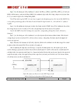
and then follow the steps shown in Figure 6-12. Connection method for drive test. The test waveforms of each key
device are shown in Table 6-12.
Fig.6-12 The connection of drive test circuit of 15kVA IP/OP board
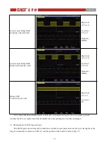
Table 6-12 The driver test description of 15kVA IP/OP board
Component and its tag number
Waveform
Remark
Charger IGBT
Q23,Q24
High level
+15V±1V
;
Low level
-8V±1V
;
Frequency
40KHz
;
If it is found that the individual IGBT drive wareform is abnormal during the drive test, please re-check
whether the device is replaced, and check whether the corresponding drive module is damaged.
6.2.3 Maintenance of 20kVA IP/OP board
20kVA IP/OP board mainly includes auxiliary power supply, charger, input filter and output filter. Among
them, the fragile components are shown in Table 6-13, and the position of the board is shown in Fig 6-13.
Table 6-13 The frogile components of 20kVA IP/OP board
Components
Tag Number
Specifications
Alternative
specification
Input/Output Fuse
F1,F2,F3,F4,F5,F6,F8,F9,F10,F11,F1
2,F13
324-0324030
Battery Fuse
F15,F16
100A/690V
Charger Fuse
F13,F14
10A/250V
Charger IGBT
Q23,Q24
IKW30N65H5
JT050N065WED
Charger Diode
D9,D10,D43,D44
RHRP3060
MM30FU60K


