background image

MANDO A DISTANCIA

REMOTE CONTROLLER

MANUAL DE 

INSTRUCCIONES

INSTRUCTION MANUAL 

GUIDE D'UTILISATION 

MANUAL D'INSTRUÇÕES

ECR05B

Escanee para ver este manual en otros idiomas y actualizaciones

Scan for manual in other languages and further updates 

Manuel dans d'autres langues et mis à jour

Manual em outras línguas e actualizações

Escanee para ver este manual en otros idiomas y actualizaciones


Scan for manual in other languages and further updates 

Manuel dans d'autres langues et mis à jour

Manual em outras línguas e actualizações
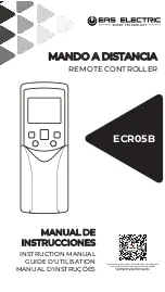
Summary of Contents for ECR05B

Page 1: ...TRUCTION MANUAL GUIDE D UTILISATION MANUAL D INSTRUÇÕES ECR05B Escanee para ver este manual en otros idiomas y actualizaciones Scan for manual in other languages and further updates Manuel dans d autres langues et mis à jour Manual em outras línguas e actualizações ...

Page 2: ......

Page 3: ...ndo a distancia Lea atentamente este MANUAL DE INSTALACIÓN Y USUARIO antes de su uso ya que le explicará cómo usar el mando adecuadamente y le ayudará en caso de que ocurra algún fallo Tras leer el manual consérvelo para su futura referencia ...

Page 4: ...ción de la unidad interior y ajustes Configuración de parámetros del mando a distancia Consulta de códigos de capacidad de la unidad interior Función de comprobación de parámetros de la unidad interior 8 8 9 FUNCIONAMIENTO DEL MANDO A DISTANCIA Precauciones de uso Modelo y parámetro Nombre y funciones de los botones Nombre y funciones de los iconos de la pantalla Métodos de funcionamiento 3 3 6 8 ...

Page 5: ...es del mando se ven con facilidad Asegúrese de que no hay fuentes de luz ni lám paras fluorescentes cerca del receptor Asegúrese de que el receptor no está expuesto a la luz solar directa 1 Precauciones de instalación Consideraciones de seguridad Lea estas instrucciones de seguridad atentamente antes de instalar el mando y asegúrese de instalarlo correctamente Tras completar la instalación comprue...

Page 6: ...a que la transmisión se ha realizado correctamente No deje caer el mando al suelo ni que se moje podría dañarse Nunca presione los botones del mando a distancia con ningún objeto puntiagudo o el mando podría dañarse Lugar de instalación La señal podría no recibirse correctamente en salas que tengan iluminación electrónica fluorescente Consúltelo con su distribuidor antes de comprar nuevas luces fl...

Page 7: ...uebe que tiene todas las piezas siguientes 3 Dimensiones del mando a distancia y el soporte Imagen 2 1 Dimensiones del mando a distancia No Nombre Diagrama Ctd Soporte 1 2 Pilas AAA 2 Manual del mando 1 Instalación Tornillos M2 9 12 3 ...

Page 8: ...nstalación y fijación 1 Use los tornillos incluidos para instalar y fijar el soporte del mando a distancia en una posición estable ver imagen 2 3 Asegúrese de seguir la sección 1 Precauciones de instala ción para determinar su ubicación Imagen 2 3 Instalación 4 ...

Page 9: ...o a distancia verticalmente en el soporte ver imagen 2 4 Imagen 2 4 5 Cambiar las pilas 1 Deslice la cubierta frontal del mando para abrirlo en la dirección indicada por la flecha ver imagen 2 5 Imagen 2 5 Instalación 5 ...

Page 10: ...e las pilas gastadas e introduzca dos nuevas pilas AAA respetando la polaridad indicada ver imagen 2 7 Cierre la tapa de las pilas Imagen 2 7 2 Retire la tapa del compartimento de las pilas ver imagen 2 6 Instalación 6 ...

Page 11: ...a que pueden dañarlo o deformarlo Si el mando tiene algún fallo de funcionamiento apa gue el mando y póngase en contacto con su distribuidor Extraiga las pilas antes de limpiar o realizar el mante nimiento del mando No lave el mando con agua ADVERTENCIA Tenga en cuenta que una exposición directa y prolongada a aire excesivamente frío o caliente del aire acondicionado puede ser dañino para su salud...

Page 12: ...os plantas animales u obras de arte ya que esto puede afectar negativamente a su rendimiento calidad y o vida útil Ventile la zona de cuando en cuando y tenga precaución cuando use el aire acondicionado en conjunto con otros aparatos de calefacción Una ventilación insuficiente puede resultar en un déficit de oxígeno ATENCIÓN Modelo ECR05B Tensión nominal 3 0 V AAA battery x 2 Rango de funcionamien...

Page 13: ...3 Botones y funciones Imagen 3 1 Apariencia del mando 8 9 15 16 1 2 3 10 11 4 5 6 7 12 13 14 Funcionamiento del mando 9 ...

Page 14: ...lventiladory lospasosdeajustedetemperatura Resistenciaaux Activaodesactivalafunción deresistenciaauxiliar SeleccióndeSólo Frío FríoyCalor CambiaentrelosmodosSólo FríooFríoyCalor On off Enciendeyapagalaunidad Velocidaddel ventilador Ajustedelavelocidaddel ventilador Temporiz OFF Configuralahoradeapagado delaunidad Direccióndelaire Ajustalaposicióndelas lamas Swing Activaodesactivalafunción swing SE...

Page 15: ... actual Transmisiónde señal ECO IndicaquelafunciónECOestá encendida Resistenciaaux Indicaquelaresistenciaauxiliarestá activa Iconoencendido Indicaqueunaunidadestá encendida Nota Los botones y no están disponibles para las unidades interiores de primera generación 4 Iconos y funciones de la pantalla Indicalaseñaldelmando enviadaalaunidadinterior Funcionamiento del mando 11 ...

Page 16: ...la pantalla del mando y la unidad interior se apagará Figura 3 3 5 2 Modo y temperatura 1 Pulse ver Figura 3 4 La pantalla mostrará el modo de funcionamiento Figura 3 4 Temporizador On Off Fan speed Indica la velocidad actual del ventilador Indica que los botones del mando están bloqueados Swing Indica que el Swing está activado Funcionamiento del mando 12 Indica las horas de encendido apagado de ...

Page 17: ...o vea los ajustes iniciales para saber cómo configurarlo 5 3 Velocidad del ventilador Figura 3 6 1 7 velocidades La configuración predeterminada del man do tiene 7 velocidades del ventilador con cada pulsación del botón cambiarán según la Figura 3 7 Auto Frío Calor Dry Fan Figura 3 7 2 3 velocidades La velocidad del ventilador se configurará según se muestra en la Figura 3 8 Auto Veloc 7 Veloc 6 V...

Page 18: ...as verticales Cuando la unidad está apagada el botón es inválido ya que el mando a distancia desactiva automáticamente la función de dirección de las lamas 5 5 Activación del swing 1 Con la unidad encendida pulse ver Figura 3 10 Se inicia la función swing y se iluminará el icono enviando la señal a la unidad interior Funcionamiento del mando 2 Con el swing encendido pulse para desactivarlo Nota Cu...

Page 19: ...modo Silencio La pantalla mostrará el icono 5 6 Display de la unidad interior El botón Display se usa para controlar el estado de encendido o apagado del display de la unidad interior 1 Con el mando en estado encendido o apagado pulse ver Figura3 11 parailuminareldisplaydelaunidadinterior Funcionamiento del mando Figura 3 12 2 En modo Silencio pulse para desactivar la función y el icono dejará de ...

Page 20: ...nsigna en 26 C cuando se activa el modo ECO en modo calefacción la velocidad es AUTO y la temperatura no cambia Pasadas 8 horas dejará de mostrarse el icono y la unidad saldrá del modo ECO automáticamente Las funciones ECO y Silencio no pueden funcionar al mismo tiempo 5 9 Temporizador de encendido y apagado El temporizador se usa para configurar el encendido o apagado programado de la unidad inte...

Page 21: ...temporizador se envía a la unidad interior Nota Mantenga pulsados los botones de ajuste del tempori zador para ajustar el tiempo en fracciones de 0 5 horas Si el ajuste sobrepasa las 10 horas los cambios se harán en fracciones de 1 hora La configuración máxima es de 24 horas Ajuste el temporizador de encendido o de apagado a 0 0h para cancelarlo Cuando se completan los ajustes del temporizador pue...

Page 22: ...o Cuando los botones del mando a distancia están bloqueados cualquier pulsación de los mismos es inválida excepto de los botones de Bloqueo selección de Sólo Frío Frío y Calor y la configuración de la dirección de grupo 1 Pulse para bloquear los botones ver Figura 3 17 y el display mostrará el icono de bloqueo Funcionamiento del mando Figura 3 17 2 Pulse de nuevo y el icono de bloqueo desaparecerá...

Page 23: ...lor 1 En el modo Sólo Frío pulse para encender la función de Frío y Calor ver Figura 3 18 Funcionamiento del mando 1 En el modo de calefacción pulse el botón ver Figura 3 19 y la pantalla mostrará el icono la señal se enviará a la unidad interior 2 Pulse de nuevo la pantalla mostrará el icono de bloqueo y la señal se enviará a la unidad interior 3 Pulse una tercera vez y la pantalla mostrará el ic...

Page 24: ...rior Mantenga el mismo botón pulsado de nuevo durante 5 segundos para salir de la página Ajustes de la instalación 1 Consulta de dirección de la unidad interior Una vez en la página de ajuste de dirección pulse para acceder a la página de Envío En ella pulse para enviar el comando de consulta ver Figura 4 2 y la unidad interior mostrará la dirección actual de la unidad interior 20 ...

Page 25: ... ajuste de dirección pulse para acceder a la página de Envío En ella pulse y para ajustar la dirección aumentando o disminuyendo el valor respectiva mente Pulse para enviar la dirección a la unidad interior Ver Figura 4 3 Figura 4 3 Ajustes de la instalación 21 ...

Page 26: ...do y al mismo tiempo durante 8 segundos para acceder a la página de ajuste de parámetros ver Figura 4 4 Cuando haya terminado la configuración pulse o espere 5 segundos para guardar los ajustes de los parámetros La secuencia de funcionamiento de los botones es la que se muestra en la Figura 4 5 Figura 4 4 22 Pulse y para ajustar los valores del parámetro ...

Page 27: ...1 3 velocidades fracción de ajuste de temperatura de 1 C 02 7 velocidades fracción de ajuste de temperatura de 1 C predeterminado 03 3 velocidades fracción de ajuste de temperatura de 0 5 C 3 velocidades fracción de ajuste de temperatura de 1 C modo Auto 7 velocidades fracción de ajuste de temperatura de 1 C modo Auto 3 velocidades fracción de ajuste de temperatura de 0 5 C modo auto 04 05 06 07 7...

Page 28: ...ámetros avanzados C1 se mostrará en la sección de temperatura del display ver Figura 4 6 Pulse para salir del estado de ajustes de pará metros avanzados Ajustes de instalación Pulse y para ajustar el código de parámetro Pulse para acceder a la interfaz de ajuste de parámetros luego pulse y para ajustar el valor de los parámetros Consulte la lista de ajuste de parámetros para seleccionar los paráme...

Page 29: ... posición de ese switch la que determina el valor de este parámetro Valor por defecto Significa que este parámetro no dispone de switch en la PCB principal y en caso de que no se realice un ajuste manual prevalecerá el valor por defecto Tiempo de parada del ventilador de la unidad interior en modo calefacción y Grado de apertura de la EXV son dos ajustes que se excluyen mutuamente por lo que el úl...

Page 30: ...03 04 FF Compensación de la tem peratura de calefacción de la unidad interior 6 2 6 4 0 6 C5 6 2 6 4 0 6 00 00 01 FF 0 2 0 Compensación de la tempe ratura de refrigeración de la unidad interior 0 2 0 C6 00 00 01 FF Función de reinicio auto mático de la ud interior C7 Habilitar deshabilitar depender de la unión J1 en la PCB de la ud interior 01 00 01 02 FF 56P 72P 0P 72P C8 72P 72P 72P 72P Selecció...

Page 31: ...dad interior mostrará el código de capacidad de la unidad interior actual Figura 4 9 3 Consulta del código de capacidad de la unidad interior Mantenga pulsados y durante 8 segundos al mismo tiempo ver Figura 4 8 para acceder a la página de consulta de código de capacidad de la unidad interior Vuelva a mantenerlos pulsados durante 8 segundos para salir de la página 27 ...

Page 32: ... y alavezdurante8segundosparaaccederalapáginadeajustede parámetrosavanzados luegopulse paraenviarlaordenyel displaydelaunidadinteriormostrarálosparámetrosactualesdela misma correspondientesalmodeloconcretodeunidadinterior Para másdetalles consulteelmanualdeinstruccionsdelaunidadinterior Ajustes de instalación 28 ...

Page 33: ...ontroller Carefully read this OPERATION AND INSTALLATION MANUAL before using the controller It will tell you how to use the controller properly and help you if any trouble occurs After reading the manual please keep it for future reference ...

Page 34: ...Batteries 9 9 9 10 10 FIELD SETTINGS Indoor Unit Address Query and Setting Parameter Configuration for Remote Controller Indoor Unit Capacity Code Query Indoor Unit Parameter Check Function 8 8 9 OPERATING THE REMOTE CONTROLLER Using Precautions Model and Key Parameters Button Names and Functions Name and Function on Display Screen Operating Methods 3 3 6 8 8 9 ...

Page 35: ...ay lamp and other indicator lamps can easily be seen Ensure that there is neither a source of light nor a fluorescent lamp near the receiver Ensure that the receiver is not exposed to direct sunlight 1 Installation Precautions Safety Considerations Please read this Safety Considerations carefully before installing Controller and be sure to install it correctly After completing the installation mak...

Page 36: ...from the receiver indicates that the transmission is properly done Do not drop or get it wet It may get damaged Never press the button of the remote controller with a hard pointed object The remote controller may get damaged Installation site It is possible that signals will not be received in rooms that have electronic fluorescent lighting Please consult with the salesman before buying new fluore...

Page 37: ...at you have all the following parts 3 Dimensions of Remote Controller and Bracket Figure 2 1 Dimensions of remote controller No Name Schematic Qty Screw lid 1 2 AAA battery 2 Remote controller manual 1 Installation Philips head screw M2 9 12 3 ...

Page 38: ...acket 4 Installation and Fixing 1 Use the screws accessories to fix and secure the remote controller bracket in a stable position see Figure 2 3 Make sure you refer to 1 Installation Precautions to deter mine the location Figure 2 3 Installation 4 ...

Page 39: ...rtically down into the remote controller bracket see Figure 2 4 Figure 2 4 5 Replace the Batteries 1 Slide open the front cover of the remote controller in the direction indicated by the arrow see Figure 2 5 Figure 2 5 Installation 5 ...

Page 40: ...re 2 6 3 Take out the old battery and install two new AAA batteries matching the indicated polarity see Figure 2 7 Close the battery cover Figure 2 7 2 Remove the battery cover see Figure 2 6 Installation 6 ...

Page 41: ...se may cause the device to become deformed If there is a fault with the remote controller turn off the remote controller and contact your local agent Remove the dry batteries before cleaning or maintenance of the remote controller Do not wash the controller with water WARNING Note that prolonged direct exposure to cool or warm air from the air conditioner or to air that is too cold or warm can be ...

Page 42: ...ood plants animals or works of art as this may adversely affect the performance quality and or lifespan of the object concerned Ventilate the area from time to time Be careful when you use the air conditioner with other heating equipment Insufficient ventilation may result in oxygen deficiency CAUTION Product Model ECR05B Rated Voltage 3 0 V AAA battery x 2 Ambient Temperature 5 to 43 C Ambient Hu...

Page 43: ...3 Button Names and Functions Figure 3 1 External view of remote controller 8 9 15 16 1 2 3 10 11 4 5 6 7 12 13 14 Operating the Remote Controller 9 ...

Page 44: ...dtemperature adjustmentsteps Auxiliaryheater Turnon offtheauxiliary heaterfunction CoolingOnly Coolingand HeatingSelection SwitchbetweenCoolingOnly CoolingandHeatingmodes On offswitch Switchon offtheunit Fanspeed Fanspeedsetting Timeroff Setthetimetoturnofftheunit Fandirection Adjustthedirectionof thelouver Swing Turnon offtheswingfunction SET Adjustupwards Adjustthetemperature settingortimer prog...

Page 45: ...ysthecurrentoperatingmode Signaltransmission ECO ShowsthatECOfunctionison Auxiliaryheater Showsthatauxiliaryheaterison Power ondisplay Indicatesaunitisturnedon Note The buttons and are not available for first generation indoor units 4 Name and Function on Display Screen Displayssignalsenttotheindoor unitfromtheremotecontroller Operating the Remote Controller 11 ...

Page 46: ...isplay screen of the remote controller and the indoor unit stops running Figure 3 3 5 2 Mode and Temperature Operations 1 Press see Figure 3 4 Display screen shows the opera ting mode Figure 3 4 Timer On Off Displays times to turn on off the unit Fan speed Displays the current fan speed Shows that the remote controller button is locked Swing Shows that Swing is on Operating the Remote Controller 1...

Page 47: ...settings for how to set the Auto mode 5 3 Fan Speed Operations Figure 3 6 1 7 fan speeds The default in the remote controller is the mode with 7 fan speeds where the Fan Speed will be adjusted in turn as shown in Figure 3 7 Auto Cool Heat Dry Fan Figure 3 7 2 3 fan speeds Fan Speed will be adjusted in turn as shown in Figure 3 8 Auto Speed 7 Speed 6 Speed 5 Speed 4 Speed 2 Speed 1 Auto Speed 3 Hig...

Page 48: ...ith vertical louvers When the unit is off the button is invalid When the unit is turned off the remote controller automatically turns off the louver direction function 5 5 Swing Operations 1 When the unit is on Press see Figure 3 10 Start the swing function and the icon will light up and signal is sent to the indoor unit Operating the Remote Controller 2 When the swing is on press to turn off this...

Page 49: ...art the Silent function Screen displays the icon 5 6 IDU Display Operations The Display function is used to control the on off state of the display in the indoor unit 1 When the remote controller is in on or off state press see Figure3 11 andthedisplayoftheindoorunitlightsup Operating the Remote Controller Figure 3 12 2 In Silent mode press to turn off the Silent function and the icon will disappe...

Page 50: ...re is 26 C in heating mode when ECO is set up the Fan Speed is turned to Auto and the temperature does not change Once it has been running for 8 hours will no longer light up and the unit will exit the ECO mode The Silent and ECO functions cannot be implemented at the same time 5 9 Timer On Off Operations Timer is used to set the timed on off state of indoor unit 1 Timer On Operation Press see Fig...

Page 51: ...ation is sent to the indoor unit Note Long press the timer adjustment buttons to adjust the time in units of 0 5 hours If the adjustment exceeds 10 hours the changes will be in units of 1 hour and the maximum time setting is 24 hours Adjust the Timer On or Timer Off to 0 0h to cancel the Timer On or Timer Off settings When the Timer settings have been completed there may be a 15 minutes time diffe...

Page 52: ...ons Operations Once the buttons on the remote controller are locked all the other button operations are invalid except for Lock Cooling Only Cooling and Heating Selection and Group Address Setting 1 Press to lock the buttons see Figure 3 17 and the display will show the lock icon 2 Press again and the lock icon will disappear Buttons are unlocked Operating the Remote Controller Figure 3 17 18 ...

Page 53: ...tion Operations 1 In Cooling Only mode press to turn on the Cooling and Heating function see Figure 3 18 Operating the Remote Controller 1 In Heating Mode Press the button see Figure 3 19 and the screen will display the icon the signal is sent to the indoor unit 2 Press again and the screen will display the lock icon the signal is sent to the indoor unit 3 Press a third time and the screen will di...

Page 54: ...ttings page of the indoor unit Long press the same button again for 5 seconds to exit the page Field Settings 1 Indoor Unit Address Query Once in the address setting page press to enter the Send page In Send page press to send the query command see Figure 4 2 and the indoor unit display will show the IDU s current address 20 ...

Page 55: ...tting Once in the address setting page press to enter the Send page In Send page press and to adjust the address up and down respectively Press to send the address to the indoor unit See Figure 4 3 Figure 4 3 Field Settings 21 ...

Page 56: ...Configuration Method Long press and at the same time for 8 seconds to enter the parameter settings page see Figure 4 4 Press and to adjust the parameter value Once the adjustment is done press or wait for 5 seconds to save the parameter settings The operation sequence for the buttons is as shown in Figure 4 5 Figure 4 4 22 ...

Page 57: ... 5 C 01 3 fan speeds temperature adjustment step of 1 C 02 7 fan speeds temperature adjustment step of 1 C default parameter 03 3 fan speeds temperature adjustment step of 0 5 C 3 fan speeds temperature adjustment step of 1 C Auto Mode 7 fan speeds temperature adjustment step of 1 C Auto Mode 3 fan speeds temperature adjustment step of 0 5 C Auto Mode 04 05 06 07 7 fan speeds temperature adjustmen...

Page 58: ...ter settings page C1 will be displayed in the temperature display area see Figure 4 6 Press to exit the advanced parameter settings status Field Settings Press and to adjust the parameter code Press to enter the parameter setting interface then press the and keys to adjust the parameter value refer to the advanced parameter setting list to select the setting para meters see Figure 4 7 Figure 4 7 F...

Page 59: ... this setting has a corresponding dial switch on the IDU PCB and the position of the switch determines the value of this parameter Default Value It means this parameter does not have a dial switch on the main PCB and in case of no setting the default value shall prevail The indoor unit fan stop time in heating mode and the Opening Degree of EXV are two mutually exclusive settings The setting which...

Page 60: ... 24 26 15 C4 14 12 16 18 14 00 00 01 02 03 04 FF Indoor unit heating temperature compensation 6 2 6 4 0 6 C5 6 2 6 4 0 6 00 00 01 FF 0 2 0 Indoor unit cooling temperature compensation 0 2 0 C6 00 00 01 FF Indoor unit Auto restart function C7 Enable Disable Depend on the J1 junper on pcb of IDU 01 00 01 02 FF 56P 72P 0P 72P C8 72P 72P 72P 72P Opening selection of electronic expansion valve for heat...

Page 61: ...re 4 9 and the indoor unit display will show the IDU current capacity code Figure 4 9 3 Indoor Unit Capacity Code Query Long press and for 8 seconds at the same time see Figure 4 8 to enter the capacity code query page of the indoor unit Long press the same button again for 8 seconds to exit the page 27 ...

Page 62: ...ether for 8 seconds to enter the advanced parameter setting page then press the to send the command and the indoor unit display will show the IDU current parameters corresponding to particular IDU model for more information refer to IDU installation and operation instruction Field Settings 28 ...

Page 63: ......

Page 64: ...A Escanee para ver este manual en otros idiomas y actualizaciones Scan for manual in other languages and further updates Manuel dans d autres langues et mis à jour Manual em outras línguas e actualizações Toda la documentación del producto Complete documents about the product Documentation plus complète sur le produit Mais documentação do produto ...

Reviews: