background image

Operator’s Manual

BADGER Front Tine Tiller

23

For additional information visit online at www.getearthquake.com or call 800-345-6007 M-F 8-5 CST

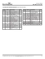
ITEM

NO.

PART #

DESCRIPTION

QTY.

1

400023

NUT M8 NYLOCK

4

2

3316

BOLT M8 X 1.25 X 45 HEX HEAD

4

3

13905

TINE OUTER RIGHT

1

4

13903

TINE INSIDE

2

5

13904

TINE OUTSIDE LEFT

1

6

13599

NUT M6 X 1.0 NYLOCK

9

7

13600

BOLT M6 X 1.0 X 25 HEX HEAD

9

8

--

ORDER PART NUMBER 13586 TRANSMISSION

1

9

--

ORDER PART NUMBER 13586 TRANSMISSION

1

10

1810

SNAP RING 1 INCH

2

11

13902

BEARING, BALL 25MM ID 6005RS

2

12

14421

SPACER 25MM X 35MM X 5.43MM THICK

2

13

13615

GEAR, BRONZE 25MM ID 6MM KEY 30 TEETH FT

1

14

17990

KEY 6X10 X25MM HALFMOON

1

15

13612

TINE SHAFT 25MM OD 6MM KEY 

1

16

3220

BEARING 20X47X15.2 TAPERED ROLLING 30204

2

17

17991

BOLT M8 X 1.25 X 30 HEX HEAD

1

18

1916965

WASHER SPRING LOCK 3/8”

1

19

803

WASHER 5/16 ID X 1-1/2” OD FLAT 16 GA

1

20

13619

PULLEY, TRANSMISSION, SINGLE GROOVE

1

21

3309

BEARING 20MM ID X 42MM OD 6004 2RS

1

22

8924

RETAINING RING 3/4” EXTERNAL

1

23

13590

SPACER, ROUND STEEL 26 X 20.22 X 6.8MM

1

24

17989

KEY 5MM X 5MM X 20MM

1

25

13610

DRIVESHAFT WORM 20MM OD

1

26

13586

TRANSMISSION 7.5:1 WORM BRASS 25MM SHAFT

1

27

21825

BOX, OUTER TINES, WHEEL SHAFT, DRAG STAKE

1

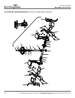
ILLUSTRATED PARTS BREAKDOWN: TINES AND TRANSMISSION ASSEMBLY

Summary of Contents for Badger 24736

Page 1: ...S TORQUE BRIGGS STRATTON 7 25 FT LBS GROSS TORQUE SN P N 22745 ECN 11380 REV3 10 24 16 2016 Ardisam Inc All Rights Reserved GAS OIL RATIO 50 1 Get more information online at www getearthquake com Operator s Manual Original Operating Instructions BADGER Front Tine Tiller ...

Page 2: ... Number Serial Number Date of Purchase Notes Record the product model number and serial number in the space provided for easy reference when ordering parts or requesting technical support Excluding emissions related warranty items the warranty is valid only if the completed registration is received by Ardisam within 30 days of purchase SEE WARRANTY SECTION FOR MORE INFORMATION You can register you...

Page 3: ...serted throughout the text Anyone who uses this machine must read the instructions and be familiar with the controls Intended Use Foreseeable Misuse IMPORTANT This is a motorized rotary tiller that works the soil by means of rotating tines It is pedestrian controlled but not self propelled with a gasoline fueled internal combustion engine to power the tines It shall not be used for any other purpo...

Page 4: ...approved by the manufacturer Operate only in daylight or good artificial light Do not operate product when fatigued or under the influence of alcohol drugs or other medication which can cause drowsiness or affect your ability to operate this machine safely Never operate machine in wet grass Always be sure of your footing keep a firm hold on the handle and walk never run Watch for traffic when oper...

Page 5: ...ed area Never fill your fuel tank with fuel indoors Examples include basement garage barn shed house porch etc Never fill tank near appliances with pilot lights heaters or other ignition sources If the fuel has to be drained this should be done outdoors The drained fuel should be stored in a container specifically designed for fuel storage or it should be disposed of carefully Always wipe up exces...

Page 6: ... precautions when leaving the machine unattended Disengage control lever stop the engine wait for all moving parts to stop and make certain guards and shields are in place When leaving the operating position for any reason Shut off the engine Wait for all moving parts to stop MAINTENANCE AND STORAGE Keep machine attachments and accessories in safe working condition Check shear bolts engine mountin...

Page 7: ...t safely and effectively we have placed several safety labels on the tiller to remind you of this important information while you are operating the unit These important safety labels are illustrated below and are shown here to help familiarize you with the location and content of the safety messages you will see as you perform normal tilling operations Please review these decals now and if you hav...

Page 8: ...r Ear and Eye Protection At All Times H Do Not Service or Adjust Moving Parts Unless Engine is Stopped and Spark Plug Wire is Disconnected I Dress Appropriately And Wear Sturdy Footwear J Toxic Fumes Do Not Operate in Unventilated Areas K Hot Surfaces L Fire Hazards M Do Not Use In Thunderstorms For severe weather stop operation of this machine and seek shelter N Team Lift For your safety always h...

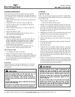
Page 9: ...d quick turning in the garden fold the wheels under the engine During operation the wheels unfold back and the drag stake folds down The long length between the tines and the drag stake make this the most comfortable handling front tine tiller on the market SEE FIGURE 1 TRANSPORT POSITION OPERATING POSITION DRIVE SAFETY CONTROL LEVER KNOBBY COMFORT GRIPS 3 POSITION HANDLE BAR HEIGHT ADJUSTMENT LAR...

Page 10: ...th sides of shield and insert both bolts and nuts in place before fully tightening SEE FIGURE 4 NOTE Dirt shield must be between engine mount deck and tine shield 6 Assemble tines to unit a Assemble outer tines to unit using two M8 bolts and two M8 nylock nuts The arrow on the tines must point in the direction of forward rotation b Outside tines have two positions wide 21 and narrow 16 For narrow ...

Page 11: ...n be assembled through one of three hole positions depending on the user s preferred handle bar height low middle high For the highest height insert bolt into the most forward hole For the lowest height insert bolt into the most rear hole SEE FIGURE 7 8 Insert depth regulator drag stake through bottom opening in lower tail mount and secure with lock pin SEE FIGURE 9 FIGURE 4 Dirt Shield Tine Shiel...

Page 12: ...URE 10 1 To increase belt tension loosen upper jam nut in1 8 increments while holding lower jam nut in place SEE FIGURE 11 2 Check adjustment and instructions under Check Belt Tension section This procedure can be repeated until conduit adjustment bolts have no more adjustment left If no more adjustment can be made belt may have to be replaced Depth Regulator Drag Stake To Adjust Tilling Depth 1 R...

Page 13: ...ERKS OR LURCHES LET GO OF THE HANDLEBARS AND THE DRIVE CONTROL LEVER IMMEDIATELY SO THAT THE TINES STOP TURNING CAUTION MUST BE TAKEN WHEN SELECTING TILLING DEPTH LOSS OF CONTROL COULD RESULT IF YOU ATTEMPT TO TILL IN CERTAIN SOIL CONDITIONS WITH THE DRAG STAKE SET IN TOO HIGH OF A POSITION STOP THE ENGINE AND REMOVE SPARK PLUG WIRE BEFORE REMOVING MATERIAL FROM THE TINES BY HAND OR ANY OTHER METH...

Page 14: ...and bolts are secure NOTE All hardware nuts bolts etc should be checked for tightness before each use Vibration of machine can cause them to loosen 2 Check oil level in engine crankcase See your engine manual for procedure and specifications 3 Inspect air cleaner for cleanliness See your engine manual for procedure 4 Check the fuel level Fill the fuel tank no closer than one inch from top of tank ...

Page 15: ... 17 EM X X Check oil level change oil 17 EM X 1 Clean tine axle shaft 17 X X Lubrication 17 X EM See engine manual 1 Change oil after the first three to five hours of use then after every 50 hours or every season Change oil every 25 hours when operating under heavy load or in high temperatures SERVICING THE ROTOTILLER The following information will help you make the necessary checks and perform th...

Page 16: ...re length of the cable link compression spring when in its relaxed state 4 Pull down on drive safety control lever and measure length of spring when compressed Ideal length would be 1 4 shorter SEE FIGURE 13 Change Belt 1 Turn off engine Engine must be cool 2 Remove spark plug wire from spark plug and secure 3 Remove front belt cover and dirt shield plate from tiller frame SEE FIGURE 14 a Remove t...

Page 17: ...xle grease 2 Drainfuelsystemcompletelyfollowingenginemanufacturer s instructions or add fuel stabilizer to prevent fuel from gumming up during extended storage period Run engine for at least 5 minutes to distribute fuel stabilizer mixture throughout entire fuel system 3 While engine is still warm drain the oil from the engine Refill with fresh oil that is recommended in engine manual 4 Clean exter...

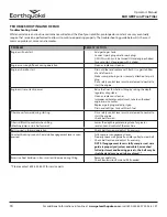
Page 18: ...e released to neutral to start the engine Check belt tension Tiller is difficult to control when tilling Machine jumps or lurches forward Lower the depth regulator drag stake for greater resistance and control of the machine Belts squeal in forward operation Check belt tension and adjust if necessary Constant buzzing sound is heard while engagement lever is com pressed Fully compress engagement le...

Page 19: ...tallation alteration accident acts of God or other events beyond Ardisam s control vandalism unauthorized parts failure to use proper fuel and oil or if repairs have been performed at a non authorized service facility These warranties shall not cover damage from normal wear and tear normal maintenance parts and services lightning nor improper installation operation storage or maintenance nor opera...

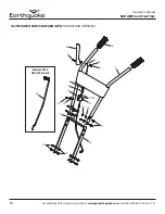
Page 20: ...iller 20 For additional information visit online at www getearthquake com or call 800 345 6007 M F 8 5 CST ILLUSTRATED PARTS BREAKDOWN HANDLEBAR ASSEMBLY 1 2 5 6 7 4 3 17 16 15 18 19 20 14 13 12 10 14 21 11 9 8 22 Model 24736 ON OFF Switch ...

Page 21: ...58 NUT M5 X 0 8 NYLOCK 1 9 53620 SPRING COMPRESSION FOR WARD ARM 1 10 4620 JAM NUT M8 X 1 25 2 11 53629 BRACKET CABLE MOUNT 1 12 W1200114 WASHER M8 X 1 9 1 13 12770 BOLT M8 X 1 25 X 40 HEX HEAD 1 ITEM NO PART DESCRIPTION QTY 14 20827 KIT CABLE M5 END M8 MOUNT 905 5 MM lONG 1 15 400023 NUT M8 NYLOCK 4 16 3245 WASHER M8 X 24X 2 2MM 4 17 13906 BOLT M8 X 1 25 X 20 4 18 3358 MOUNT HANDLEBAR 1 19 W1265V...

Page 22: ... For additional information visit online at www getearthquake com or call 800 345 6007 M F 8 5 CST ILLUSTRATED PARTS BREAKDOWN TINES AND TRANSMISSION ASSEMBLY 1 2 27 4 1 2 4 27 6 7 8 9 10 10 11 11 12 12 13 14 15 16 17 18 19 20 16 22 21 23 24 25 26 ...

Page 23: ... SPACER 25MM X 35MM X 5 43MM THICK 2 13 13615 GEAR BRONZE 25MM ID 6MM KEY 30 TEETH FT 1 14 17990 KEY 6X10 X25MM HALFMOON 1 15 13612 TINE SHAFT 25MM OD 6MM KEY 1 16 3220 BEARING 20X47X15 2 TAPERED ROLLING 30204 2 17 17991 BOLT M8 X 1 25 X 30 HEX HEAD 1 18 1916965 WASHER SPRING LOCK 3 8 1 19 803 WASHER 5 16 ID X 1 1 2 OD FLAT 16 GA 1 20 13619 PULLEY TRANSMISSION SINGLE GROOVE 1 21 3309 BEARING 20MM ...

Page 24: ...earthquake com or call 800 345 6007 M F 8 5 CST ILLUSTRATED PARTS BREAKDOWN ENGINE AND CHASSIS PARTS 2 1 44 4 5 3 6 7 35 36 43 42 37 36 35 39 38 8 10 16 15 14 9 17 13 9 8 18 21 19 22 23 25 24 26 2 27 20 32 28 14 29 28 34 33 31 41 40 45 30 9 11 12 48 49 50 45 46 47 51 Model 24736 Pulley Mount Parts ...

Page 25: ...D 2 21 1407 SPRING FORWARD ARM 1 22 53398 PIN COTTER 2MM X 16 MM 1 23 1416 PIN CLEVIS 6 3 X 16 8 MM 1 24 53596B YOKE ZINC PLATED CLEVIS 1 25 2431 WASHER M10 X 20 X 2 1 26 400024 WASHER M8 8 4 X 16 X 1 6 1 27 20835 FORWARD ARM 1 ITEM NO PART DESCRIPTION QTY 28 W1200126 WASHER M10 X 28 X 2 8 2 29 1413 PULLEY REVERSE IDLER 1 30 22563 WIREFORM BELT CATCH 1 31 W1265V0903 NUT M10 X 1 5 NYLOCK 1 32 22633...

Page 26: ...Operator s Manual BADGER Front Tine Tiller 26 For additional information visit online at www getearthquake com or call 800 345 6007 M F 8 5 CST NOTES ...

Page 27: ...Operator s Manual BADGER Front Tine Tiller 27 For additional information visit online at www getearthquake com or call 800 345 6007 M F 8 5 CST NOTES ...

Page 28: ...l information visit online at www getearthquake com or call 800 345 6007 M F 8 5 CST All weights specifications and features are approximate and are subject to change without notice Due to continuous product improvements product images may not be exact Items used for props not included Some assembly may be required ...

Reviews: