


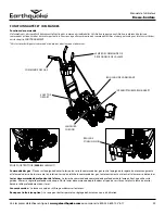

ASSEMBLY INSTRUCTIONS
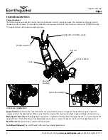
INSTALL HANDLEBAR
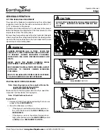
1. Position dash panel between the lower handlebar attach
points. Position the upper handlebar outside of the lower
handlebar attach points. Attach handlebars and dash panel to
the handlebar mount with 6 x M6X20 bolts and 6 x M6 nuts.
SEE FIGURE 1.
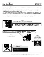
IMPORTANT
ENSURE BLADE DOES NOT TURN WHEN LEVER IS IN
TOP NOTCH (DISENGAGED) BY SLOWLY PULLING
ENGINE RECOIL AND OBSERVING THAT THE BLADE
DOES NOT ROTATE.
ASSEMBLY
UNPACKING
1. Set aside the operator’s manual and parts bag. Carefully lift
the top foam out of the box, remove all loose parts from both
the top and bottom foam packaging.
2. Parts Bag Content
Note: Ensure that all parts have been removed from
inside and underside slots of foam packaging.
KEY DESCRIPTION
23275
QTY.
24000
QTY.
1
BOLT M8 X 25
3
3
2
BOLT M8 X 30
1
1
3
BOLT M6 X 20
6
6
4
BOLT M8 X 20
1
1
5
NUT M8
5
5
6
NUT M6
6
6
7
NUT M10
2
2
8
COTTER PIN 2 MM
6
8
9
SPACER AXLE
4
2
10
SPACER WHEEL POSITION
1
1
11
DOUBLE ANGLE BRACKET
1
1
12
WASHER M12
2
5
13
STRAP CUP HOLDER
1
1
14
WASHER M10
6
6
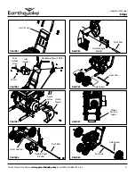
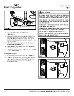
INSTALL TOOL HOLDER AND HEIGHT ADJUSTMENT
CONTROLS
2. Position the tool holder strap onto the front of the tool
holder. Then position the tool holder onto the front of the
handlebar mount plate. Position the blade height control
on the backside of the handlebar mount plate. Attach tool
holder strap, tool holder and blade height controls to the
handlebars with 3 x M8X25 bolts, 1 x M8X30 and 4 x M8 nuts.
The M8x30mm long bolt is attached through the lower left
hand side mount point on the tool holder, when standing at
the operator’s position.
SEE FIGURE 2.
INSTALL CUTTING HEAD ASSEMBLY
3. Remove the clutch shield. Connect the engine belt to the
clutch pulley. Reattach the clutch shield.
SEE FIGURE 3.
4. Position the cutting head assembly onto the pivot location
on the engine mount. Position the double angle bracket onto
the cutting head assembly. Insert the pivot rod through the
double angle bracket, cutting head assembly and engine
mount. Attach the pivot rod to the engine mount with 2 x
M10 washers and 2 x 2mm cotter pins on each end of the rod.
Attach the double angle bracket to the engine mount with 1
x M8 x 20 bolt and 1 x M8 nut.
SEE FIGURE 4 AND FIGURE 5.
NOTE THE ORIENTATION OF THE DOUBLE ANGLE BRACKET
IN FIGURE 5.
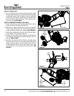
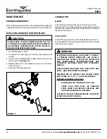
INSTALL WHEELS
5. Position the front axle with the front mount points on the
engine mount. Insert the front axle into the engine mount.
Assemble the front wheels in the following order:
1.
Axle spacer
2.
Front wheel (bearing side facing the spacer)
3.
Front wheel (bearing side facing away from the other
wheel)
4.
Axle spacer
SEE FIGURE 6.
Attach the front axle to the engine mount with
2 x M12 washers and 2 x 2mm cotter pins
6. Slide the front wheels, one to each end of the front axle. Clip
the wheel position spacer onto the front axle between the
front wheels.
SEE FIGURE 7.
7. Slide a rear wheel onto the rear axle. Slide an axle spacer
onto the rear axle up to the rear wheel. The rear wheel should
have the bearing side facing the spacer. Position the rear axle
with the rear mount points on the engine mount. Insert the
rear axle into the engine mount and through the other side.
Slide an axle spacer onto the rear axle and then another rear
wheel. Attach the rear axle with 2 x M10 nuts on each end.
SEE FIGURE 8.
Operator’s Manual
Edger
10
Check for parts online at
www.getearthquake.com
or call 800-345-6007 M-F 8-5


