


Hands
free
intercom
Lock
control
Support
2
door stations
+
slave
monitors
(
up
to
3
)
,
or
1
door station
+
2
CCTV
Color, brightness,
contrast,
volume and display mode adjustable
Real-time monitoring to door station or CCTV camera
“
Don’t disturb” function
Makeinternal
call
to
other
monitors
Broadcast
function
Monitor listening to another indoor monitor.
Touch
buttons
25 polyphonic ring-tones switch freely
3
、
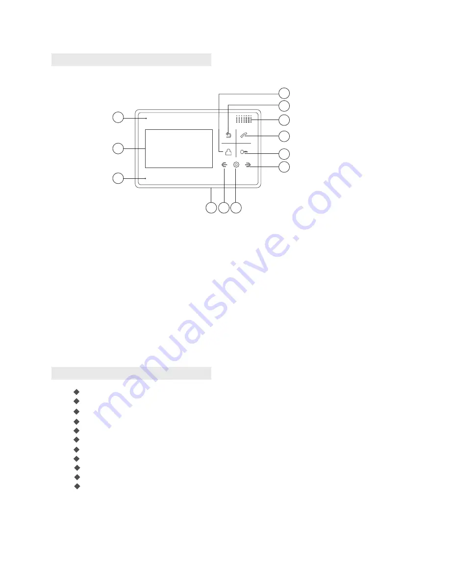
Main future and functions
1
3
5
11
10
2
4
6
12
1).
Monitor button: monitor
2).
Return button:
/hang off
Return
4).
Answer button: answer the call/
5).
Unlock button: unlock
6).
Navigation button:
7).
Indicator light: Power indicator light
10).
Setting button: Enter system
settings/Confirm
11).
Navigation button: Adjust -
7
8
9
3).
Speaker
call transfer
8).
LCD
9).
Microphone
12).
Power on/off
2
The function and name of each part
、
Page
2


