- 1
6
-
6. Illustrations & Parts List
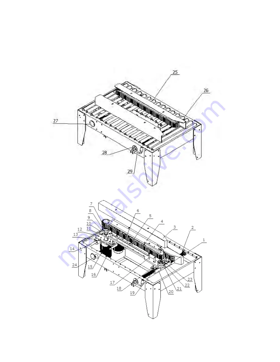
6.5 Side Conveyor System
(Continued)
Page 1: ...1 Operations Manual Eagle T200 T200L Carton Sealer READ ALL INSTRUCTIONS CONTAINED IN THIS MANUAL PRIOR TO MACHINE INSTALLATION Rev 2 2102...
Page 2: ...4 5 5 Regular Maintenance Lubrication Conveyor Belt Adjustment Carriage Height Adjustment Typical Faults Solutions 9 10 9 9 9 10 10 6 Illustrations Parts List 6 1 6 2 6 3 6 4 6 5 6 6 6 7 6 8 6 9 6 10...
Page 3: ...ceramics produce meats poultry Prior to setting up the machine 1 Verify the model number matches the model number addressed in this manual 2 Verify that no parts of the machine have been removed or a...
Page 4: ...Humidity 110VAC 50 60Hz Single Phase 30 cartons per minute 100lbs 45kg 2 3in 48 72mm 6in to infinite 6 75 30in 4 75 30in 43in 708lbs 32 104 F 0 40 C 98 Humidity 75db 75db T200 T200L Power Requirement...
Page 5: ...able to comfortably reach the roller table while maintaining approximately 4in 100mm of distance from the machine 3 3 Tape Head Installation Rest the upper tape head on the carriage placing the notch...
Page 6: ...stallation Align the holes in the extension with the posts in the frame and carefully lower the table extension 3 6 Connect Power Supply Connect the machine to the power supply Note Prior to connectin...
Page 7: ...ss slack a Belt deviation slack should be checked once every ten days b Adjust belt tension as needed 2 Vertical guide adjustment lever is firmly in place and belts do not have excess slack a Belt dev...
Page 8: ...Adjustment Adjustment Knob Loosen the knobs and move each top box squeezer in the direction of the arrows 1 and 2 Rollers should touch aka kiss the edge of the carton with a little bit of pressure Th...
Page 9: ...bearings should be lubricated once a month 3 The transmission axle driving chain and bearing should be lubricated once a week 4 All other moving parts should be lubricated on a regular basis 5 3 Conv...
Page 10: ...e carriage down 5 5 Typical Faults Solutions Fault Solution Tape is not centered on the carton Adjust the tape positioning knob on the tape head dispenser Scratched carton caused by tape cutting blade...
Page 11: ...1A 110R 2 3 Nut Plate FJG 1A 112 4 4 Leg FJG 1A 113 4 5 Rear Leg Support Must specify Left or Right FJG 1A 111L or FJG 1A 111R 1 ea 11 6 Support Shaft FJ 1A 68 1 If you have a T200L please be sure to...
Page 12: ...9 2 7 Lift Screw Bearing 6905 ZZ 2 8 Upper Supporting Board FJ 3AS 21 2 9 Lift Screw Left FJ 3AS 26 1 10 Upright Post Body FJ 3AS 24 2 11 Lift Screw Right FJ 3AS 25 1 12 Lift Body FJ 3AS 19 2 13 Idler...
Page 13: ...JG 1A 116L or FJG 1A 116R 1 5 Bolt 2 6 Spacer Washer 2 7 Squeezer Bearing 6203Z 2 8 Contact Roller FJG 1A 142 2 9 Spindle FJG 3A 143 2 FJG 3A 143B FJG 3A 143W 10 Round Nut FJG 3A 143RN 2 Description P...
Page 14: ...14 6 Illustrations Parts List 6 4 Tape Head Carriage Upper Belt Drive...
Page 15: ...2 12 Upper Tension Axle FJ 2A 123 1 13 Retaining Plate FJ 1A 703 1 14 Brush Support FJ 1A 701 1 15 Support Bars FJG 1A 131 2 2 16 Supporting Shaft FJ 1 440 1 17 Shaft FJ 3A 807 1 18 Spring Holder FJ...
Page 16: ...16 6 Illustrations Parts List 6 5 Side Conveyor System Continued...
Page 17: ...e Shaft FJ 1A 201 1 15 Lead Screw Left Right FJG 1A 154 1 16 Motor Standard RPM 1670 CV200 20ZG1 G2 2 17 Locating Pins FJG 1A 160 4 18 Connection Pole FJG 1A 162 4 19 Orientation Plate FJG 1A 158 2 20...
Page 18: ...ons Parts List 6 6 Tape Head Description Part Number Qty Complete Top Tape Head TAPE HEAD T 1 Complete Bottom Tape Head TAPE HEAD B 1 If you have a stainless steel model please add SS to any metal par...
Page 19: ...J 00 02 1 11 Shaft FJ 00 07 1 12 Shaft FJ 00 06 4 13 Side Plate x2 FJ 01 16 1 14 Shaft Cover FJ 02 09 1 15 Back Roller Side Plate Assembly see pg 21 for breakdown FG BKROLLERA 1 16 Brass Washer FJ 02...
Page 20: ...J 50 100 1 7 Phillips Flat Head Screw M4x12 1 8 Phillips Flat Head Screw M5x15 1 9 Press Tape Board FJ 01 05 1 10 Press Board FJ 01 08 1 11 Shaft FJ 00 10 1 12 Axle Sleeve FJ 02 02 2 13 Bearing 6900Z...
Page 21: ...ate Must specify Left or Right FJ 01 13L or FJ 01 13R 1 2 Shaft FJ 00 10 1 3 Back Rubber Roller FJ 40 03 1 4 Shaft FJ 00 06 1 5 Axle Sleeve FJ 02 05 1 6 Axle Sleeve FJ 02 06 2 7 Bearing 6800Z 2 8 Shaf...
Page 22: ...ley Assembly FG GUIDEPA can be order as set Description Part Number Qty 1 Shaft FJ 00 03 1 2 Axle Sleeve FJ 02 07 1 3 Bearing Bushing FJ 02 08 1 4 M5 Lock Washer M5LOCKWASHER 1 5 Socket Head Cap Screw...
Page 23: ...sion Spring FJ H 01 3 Protecting Blade Guard FJ 01 06 4 Sponges Included on FJ 01 06 5 Nut M4 6 Knife Support FJ 40 04 7 Blade standard 2 W65MM 8 Blade Carrier Block FJ 01 07 9 Socket Head Cap Screw M...
Page 24: ...rame FJ 05 00 1 2 Axle Sleeve FJ 02 12 1 3 Anti Skid Washer FJ 05 01 2 4 Tape Wheel FJ 02 05 03 1 5 Gasket FJ 05 02 1 6 Press Spring FJ H 08 1 7 Adjuster Shaft FJ 00 14 1 8 Bearing Bush FJ 02 08 1 9 M...
Page 25: ...art when ordering 6 14 Tape Holder Assembly Description Part Number Qty 1 Shaft FJ 00 09 1 2 Press Tape Board FJ 01 05 1 3 Torsion Spring FJ H 03 1 6 15 Tape Guide Assembly Description Part Number Qty...
Page 26: ...1 10A N2 N1 5 5 1 6 2 2 1 SB3 U1 N1 6 KM1 0910 M7N 5 6 W1 N1 L11 D0910 LC1 3 4 5 6 7 9 10 11 12 L N U1 W1 N1 1 2 2 SB2 HL N N2 L R QS SB1 2010 01 12 TN2 B1 13 1 14 5 6 15 2 1 U1 8 W1 26 Start Stop Eme...
Page 27: ...1 W1 0 2KW The emergency stop switch in the dotted line box is optional which shall be specified in the order Notes 1 The character with an underline e g 0 means the wiring number of contact point 0 2...