SHENZHEN EAGER LED CO., LTD.
LED Display Factory
Web:
www.eagerled.com
Outdoor LED Screen
,
Indoor LED Screen
,
Outdoor LED Module
,
Indoor LED Module,
LED Control System
,
Commercial LED Screen
,
Rental LED Screen
,
Curved LED Screen
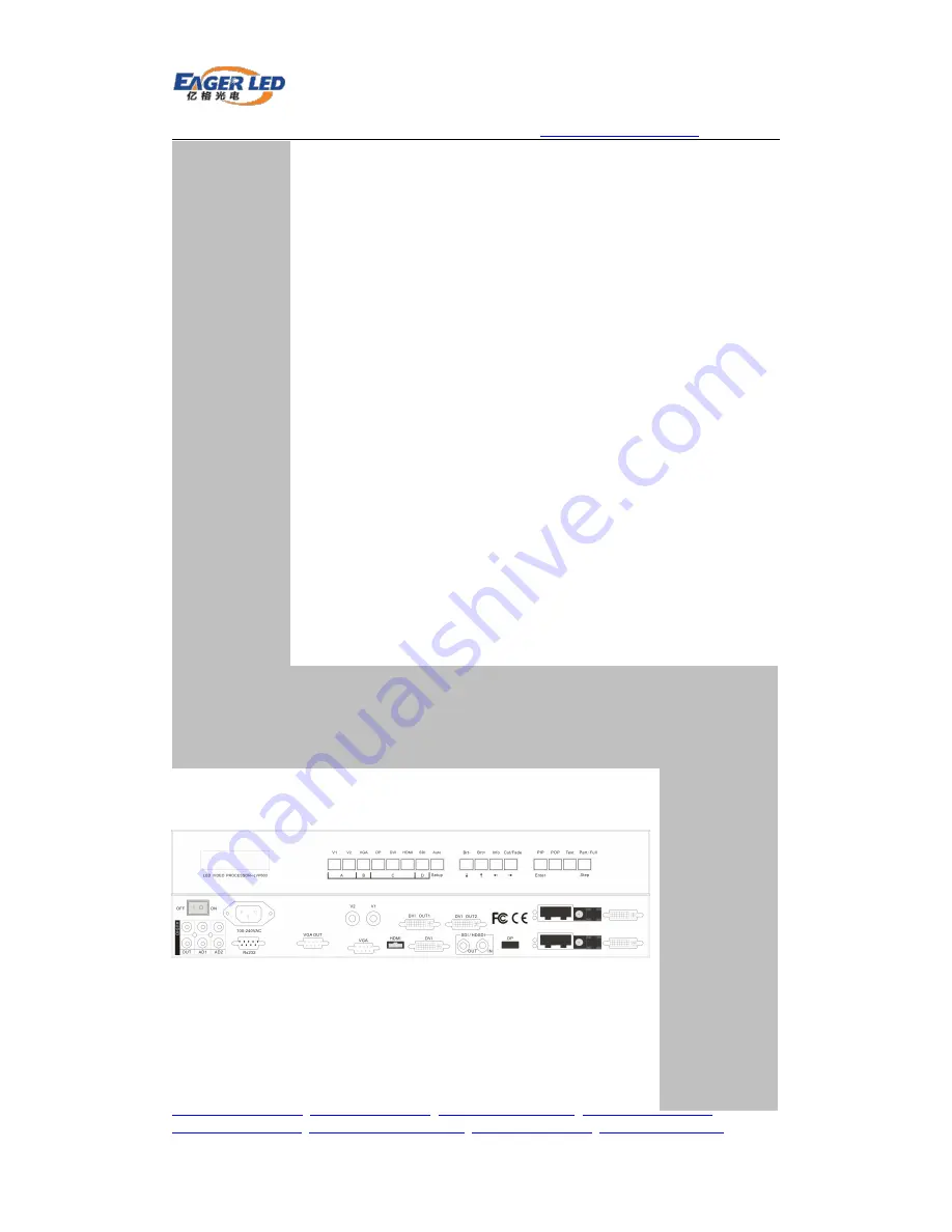
LVP603S
LED Video Processor
USER’S MANUAL


