background image

-

11

-

www.eachine.com

Quick


Start


Guide

V-tail 210 

8.0 Ready for Flight

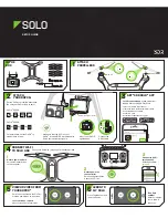
Install propeller 

Fix the 5045BN propeller (Counterclockwise) 

onto the M1

(

CW


motor


Inverted


mounted

M4 motor (CCW motor), and fix the 5045BNR 

propeller (Clockwise) onto the M2(CW motor),

M3 motor (CCW motor Inverted mounted) 

Counterclockwise to tighten the Black propeller 

Locking Nut and Clockwise to tighten the Silver 

propeller Locking Nut. Tighten the propeller 

locking nut manually and make sure the 

propeller is installed in proper way and fastened.

IMPORTANT NOTES:

The side which marked characters must be up

5045BNR

5045BN

5045BNR

5045BN

M4

(

CCW motor

)

M2

(

CW motor

)

M3

(

CCW motor Inver ted mounted

)

M1

(

CW


motor


Inver ted


mounted

)

Batter y installation

First put the battery anti-slip mat into the bottom carbon board.

Put the battery at the bottom and move it forward-backwards as required for perfect balance and No 

interference with other equipment then firmly secure the battery with the velcro strap.

Attention:

(1)Place the aircraft in a wide open space, with the rear facing you.(This position is known as “TAIL IN”)

(2)Put SWB switch to the 2 position (Please set the flight model to stabilize if yours are not RTF Version)

put all trims and dials to the Middle position, move the throttle to the lowest position, then turn on the 

Remote Controller.

(3)A video receiving equipment is needed(such as FPV monitor with 5.8G wireless video receiver ,

Goggles glasses ,etc.)to display an image and OSD information.

(4)The V-tail 210 mini-quad have a low-voltage alarm beeper. And the OSD give you a visual reference 

for the remaining battery power、fight time, flight height, attitude line, flight speed, Coordinates, 

direction. When voltage reach below 14.0 volts and the beeper will sound alarm. The V-tail210 

mini-quad is designed for FPV racing there is no “automatic landing mode".

Summary of Contents for V-tail 210

Page 1: ...EflI lINE QUICK START GUIDE www eachine com V tail 210...

Page 2: ...provide Jaw Dropping Flight Performance Internal ARM Cortex M4 72Mhz CPU with Math co processor FPU for efficient flight calculations that gets more done in less time It means that the Loop times up t...

Page 3: ...ation Flight controller specification Motor Specification Emax RS2205 KV Configuration Diameter Length Shaft Diameter Weight g Idle current 10 10V A No of Cells Li po Max Continuous Power W 180S Inter...

Page 4: ...V Records Frame rate 60Frames Compress Format MOV Video Output size 640x480 Size 50mm x 22mm Weight 6g Max support 32G TF Card Auto save function Auto save every 5 minutes 5 8G 40ch 200mw Video transm...

Page 5: ...CW 5045BNR V2106 PDB OSD V2101CCW 5045BN V2102ESC V2105 Camera V2101CW 5045BNR V2102ESC V2102ESC V2119 V2109GPS V2107 V2108 V2115 V2137 V2120 V2103 V2104 V2102 V2118 V2105 V2138 V2106 V2139R Optional...

Page 6: ...rm protection guard V tail arm Reinforcement part Front landing gear Rear landing gear Motor protection guard Rear LED guard Front LED module Rear LED module Aluminum hexagonal columns Aluminum Studs...

Page 7: ...im 10 Right stick 11 Left trim 12 Right trim 13 Up 14 press the Enter key 15 Down 16 Short press the Cancel key 17 Code keys 18 Switch 19 LCD Display 17 10 10 18 5 5 5 6 6 6 7 7 7 8 8 8 9 9 9 10 11 11...

Page 8: ...UTO SeniIPY vackbo 115200 Disabled AUTO Sena fix uLackto 115200 Disabled AUTO allSena kis 1J5EtVCP LlART1 U ART2 IJAR9 3 Receiver Mode e RX_PPM PPM RX input RX_SERIAL Serial based receiver CSPEKSAT SB...

Page 9: ...15200 Disabled AUTO Sepia RX 57600 ART2 ij MSP 115209 Mi Biackuox 115200 Disabled AUTO IIME Sena RX 57600 115200 CIDBlackbo 115 200 Disabled AUTO L_MoSeliaIRX FM Receiver Made RX_PPM PPM RX input RX_S...

Page 10: ...61 3olbox 115200 Disabled AUTO r tapsenal fix 676 00 Receiver Mode RX_P PM PPM RX input RX_SERIAL Serial based receiver SPEKSAT SBUS SUMD RX_PARALLEL_PWM PWM RX input lone wire per channel j RX_MSP MS...

Page 11: ...ring charging the Led screen will display total battery voltage and single cell voltage cyclically When charging is completed the total voltage should be 16 8v 0 1v 0 2v in the LED Screen IMPORTANT IS...

Page 12: ...e bottom and move it forward backwards as required for perfect balance and No interference with other equipment then firmly secure the battery with the velcro strap Attention 1 Place the aircraft in a...

Page 13: ...Height Filght Time Latitude Longitude Direction 9 0 Motor ARM DISARM The Vtail 210 ARF RTF was set AUX1 CH5 to ARM DISARM the motor the AUX1 CH5 of RTF Version is SWA Switch and for the ARF Version yo...

Page 14: ...ircraft disarm lock the aircraft First Power off the aircraft by unplugging the battery then turn off the radio Finally remove the battery from the aircraft 10 0 Firmware flsh for The V tail 210 The f...

Page 15: ...ailable here Contributing If you would like to help make Cleanflight even better you can help in many ways including Answering other users questions on the forums and IRC Contributing code to the firm...

Page 16: ...your computer while flashing_ re appropriate far your Ater Connect 2016 437 13 0 Detected device with total lash size 250 r f you have loss communicate on wi r 513 follow these steps to restore commu...

Page 17: ...win32 Replace Driver libusbK WinUSB Microsoft0 6 devices found Zadig 212 677 5 From Zadig a Select Options b Tick List All Devices 16 www eachine com Quick Start Guide V tail 210 6 a Select STM32 Boo...

Page 18: ...oad button and observe the serial console at the bottom of arduino Success is noted as white text on black background stating just the binary sketch size If messages in red letters appear something we...

Page 19: ...start MW OSD GUI It should connect and work normally with the newly flashed OSD Updating fonts Connect to the OSD using the GUI Select the font you require otherwise the default one will be used The...

Page 20: ...www eachine com User manual is subject to change without prior notice...

Reviews: