


_______________________________________________________________________________________________________________________________
European Safety Systems Ltd.
Impress House, Mansell Road, Acton, London W3 7QH
Tel: +44 (0)208 743 8880
www.e2s.com
Fax: +44 (0)208 740 4200
Document No. D202-00-201-IS_Issue_1 07-05-2019
Sheet 3 of 8
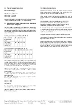
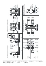
Flame Path on Cover Shown
Hatched
Flame path through shaft bore
5) Location and Mounting
The location of the call point should enable ease of access
for operation and testing. The unit should be mounted using
the 4 off fixing holes which will accept up to M5 sized fixings.
They should only be fixed to services that can carry the
weight of the unit.
To gain access to the mounting holes in the base the front
cover must be removed. See Section 6.
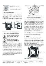
80,0 [3,15in.]
114,0 [4,49in.]
134,0 [5,28in.]
137,0 [5,39in.]
133,9 [5,27in.]
Ø6,4 [Ø0,25in.]
Fig. 1 View of base unit showing fixing centres (in mm).
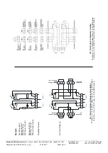
6) Access to the Flameproof Enclosure
To access the Ex d chamber, remove the four off M6 x 50
stainless steel A4-70 cap head cover bolts and withdraw the
flameproof cover taking extreme care not to damage the
flameproof joints in the process. M6 cover screws are Class
A4-70 stainless steel and only screws of this category can be
used for the enclosure.
On completion of the installation the flameproof joint surfaces
should be inspected to ensure that they are clean and that
they have not been damaged during installation.
Once the screws are removed the cover will hang down out
of the way to gain access to the terminals, the internal earth
terminal and mounting hole recesses.
Fig. 2 Accessing the Explosion proof Enclosure.
Check that the earth bonding wire between the two castings
is secure and the ‘O’ ring seal is in place.
When fitting the flameproof cover ensure the cover is sitting
flat and correctly positioned on the base. Insert the M6 x 50
stainless steel A4-70 Cap Head
cover bolts and fully
tighten down (tightening torque 3.5Nm), ensuring no gap is
visible between the cover and base of the enclosure.
The enclosure is non-conductive. These may generate an
ignition-capable level of electrostatic charges under certain
extreme conditions. The user should ensure that the
equipment is not installed in a location where it may be
subjected to external conditions that might cause a build-up
of electrostatic charges on non-conducting surfaces.
Additionally, cleaning of the equipment should be done only
with a damp cloth
.
Caution do not change factory applied finishes
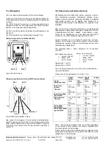
7) Earthing
The units are provided with internal and external earth
terminals which are mounted in the base of the unit.
Internal earthing connections should be made to the Internal
Earth terminal in the base of the housing using a ring crimp
terminal to secure the earth conductor under the earth clamp.
The earth conductor should be at least equal in size and
rating to the incoming power conductors.
When using the internal earth terminal ensure that the
stainless steel M4 flat washer is between the incoming earth
wire and the enclosure.
Fig 3 Earth terminals
Warning –
Hot surfaces. External
surfaces and internal components may
be hot after operation, take care when
handling the equipment.
Warning – High voltage may be present,
risk of electric shock. DO NOT open
when energised, disconnect power
before opening.
Call Point Cover
Call Point Base
M6x50 Cap head Cover Bolts - 4 off Positions
Wiring terminal
Internal Earthing
External Earthing


