Page G-1
Service Parts Manual
Ref Esc 1-1
16
17
22 21
18
1 - Includes Items 2 - 29
29
19
19
19
13
20
23
From Power
Harness
15
10 8
3
2
12
3 2
BLK
10
8
RED
From Control
Harness
WHT
6
A
A
19
26 27
M-
B-
B+
ORN to
MS4 (NC)
BLK to
Tab on
Direction
Selector
RED to
Solenoid
LT. GRN to
Key Switch
24
7
B- to Negative
Battery Terminal
12
BLK
BLK
RED
RED
WHT
M- to
A1 Motor
SOL
B+ to Direction
Selector A
To Pedal
Box Connector
11
To B+
* Silver line on
diode (6) must be
oriented as shown
*
ELECTRONIC SPEED CONTROL - SERIES
Summary of Contents for YEAR 2006+
Page 2: ......
Page 6: ...Page iv TABLE OF CONTENTS Service Parts Manual Notes...
Page 9: ...Page vii Service Parts Manual ILLUSTRATED PARTS BREAKDOWN ILLUSTRATED PARTS BREAKDOWN...
Page 23: ...Page C 4 Service Parts Manual BODY FRONT...
Page 29: ...Page C 10 Service Parts Manual BODY REAR...
Page 39: ...Page D 6 Service Parts Manual BRAKES...
Page 43: ...Page E 4 Service Parts Manual DIRECTION SELECTOR...
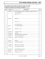
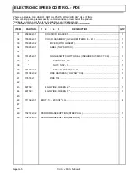
Page 57: ...Page G 6 Service Parts Manual ELECTRONIC SPEED CONTROL PDS...
Page 87: ...Appendix A 1 Service Parts Manual SPECIALTY PRODUCTS SPECIALTY PRODUCTS...
Page 89: ...Appendix A 3 Service Parts Manual SPECIALTY PRODUCTS Notes...
Page 90: ...Appendix B 1 Service Parts Manual OPTIONS ACCESSORIES OPTIONS ACCESSORIES...
Page 93: ...Appendix B 4 OPTIONS ACCESSORIES Service Parts Manual Notes...
Page 94: ......


