INSTALLING THE DRILL BIT
•
Heavy Load
:
Use handles to
reposition the drill unit. Weight of the drill unit may cause back strain if improperly lifted.
Lay the machine on one side. This gives easier access to the drill motor and bit guide.
Page 1: ...SETTING UP THE MODEL 110B...
Page 2: ...trol panel and wear safety glasses to prevent eye injury Pinch Points Keep hand clear of carriage assembly Hands or fingers caught between carriage and frame may be seriously injured Moving Parts When...
Page 3: ...mask to protect from concrete dust High Pressure High pressure from the air compressor can damage the drill and can void the warranty Lifting The Drill Unit when using a lifting device to pick up the...
Page 4: ...t air hose before disassembling or disconnecting parts IMPORTANT The chuck size of the drill bits must match the chuck size of the drill All E Z Drill Model 110B drill units have a 7 8 x 3 1 4 chuck s...
Page 5: ...e the correct bit guide bushing to match the bit you will be using For drilling a 5 8 diameter hole use 1108 MCP 3 4 diameter hole use 1109 MCP 7 8 diameter hole use 1110 MCP 1 diameter hole use 1111...
Page 6: ...DRILL BIT Heavy Load Use handles to reposition the drill unit Weight of the drill unit may cause back strain if improperly lifted Lay the machine on one side This gives easier access to the drill moto...
Page 7: ...INSTALLING THE DRILL BIT To install a drill bit loosen the swivel bolt until you can swing it out away from the lower bit guide NOTE You can use the wrench provided on the back of the control panel...
Page 8: ...INSTALLING THE DRILL BIT Flip up the retainer latch on the drill motor...
Page 9: ...INSTALLING THE DRILL BIT Place the bit into the chuck and close the bit guide and tighten the swivel bolt...
Page 10: ...INSTALLING THE DRILL BIT Close the latch on the rock drill by flipping it down back in place Pinch point...
Page 11: ...INSTALLING THE DRILL BIT You may have to adjust the return stop rod so that the end of the bit clears the bit guide...
Page 12: ...INSTALLING THE DRILL BIT To adjust the return stop rod loosen the stop rod nuts Move the stop rod in the direction needed to the required location and re tighten the nuts...
Page 13: ...INSTALLING THE DRILL BIT If you are using a 2 piece H thread bit you may also have to adjust the guide wheels by loosening the guide wheel bolt and sliding the guide wheel forward...
Page 14: ...ng the four bolts and nuts This allows the front assembly to be adjusted up or down to get the drill bit at the desired drilling location Then re tighten the four bolts and nuts Pinch Points Keep hand...
Page 15: ...JUSTING THE HEIGHT OF THE DRILL Next you can level the drill unit by loosening the two bolts on each of the rear legs Level the rear of the machine and re tighten the bolts Pinch point Keep hands clea...
Page 16: ...L SYSTEMS IMPORTANT BEFORE LEVELING THE DRILL UNIT NOTE THAT MANY TIMES THE DRILL UNIT IS NOT TO BE LEVEL WITH THE WORLD IT SHOULD BE SET TO DRILL PARALLEL WITH THE TOP OF THE CONCRETE SLAB INTO WHICH...
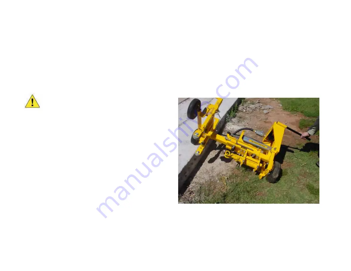
Page 17: ...ING THE DRILL DEPTH To adjust the drill unit to drill to the desired depth make sure all other adjustments have been made Maneuver the drill to the edge of the concrete slab Heavy load Use lifting han...
Page 18: ...ke sure both guide wheels are touching the concrete This ensures the hole will be perpendicular to the concrete and will maintain the desired drill depth Manually push the carriage in until the drill...
Page 19: ...SETTING THE DRILL DEPTH Adjust the stop rod so that the head of the stop rod is the desired distance from the stop pad Use a tape measure to ensure the proper depth Then re tighten the stop rod nuts...
Page 20: ...ing the wrench provided on the back of the control panel remove the oiler cap from the oiler DO NOT REMOVE CAP UNDER PRESSURE Oiler must be filled with proper rock drill oil see Recommended Specificat...
Page 21: ...20 40 to 80 F SAE 30 80 to 110 F SAE 40 Above 100 F SAE 50 Mineral Activity None Free Fatty Acid as Oleic 0 40 Max ASTM Steam Emulsion No 600 Max b Metallic Soaps None Pour Point F 10 Max c Film Stre...
Page 22: ...ler should run approximately four hours before needing refilled If you need to make an adjustment to the flow use a screwdriver to turn the screw to a higher number for more flow or to a lower number...
Page 23: ...wheel is in the way or if you skew drilling you can raise the guide wheel front handle bar by removing the lock pin on the handle bar loosen the handle set screw then raise the front handle bar Pinch...
Page 24: ...ADJUSTING THE FRONT LIFTING HANDLES Replace the lock pins and re tighten the handle set screws...