background image

FILE: IM101 service manual.doc                                                                                                  2006.01.10


E-TECH Co., Ltd                                                                                                                                      22/26


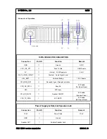
-Connector of Operation 


Power Supply & External Speaker Jack 

Connection


Pin NO 

Function 

Remark 

13.6V 

 Power 

Cable 

13.6V 

GND 

 Ground 


Speaker OUT 


External Speaker Jack 


10PIN CONNECTOR DESCRIPTION 

Connection Pin 

NO 

Function 

Remark 

GND 

 Ground 

GND 

CPU_INT_PTT 


Push To Talk 

GND Enable 

5V 


Internal    5 Volt Regulator 

5 Volt 

FLAT_AUDIO_IN/OUT 


Constant    Audio Signal Level 


S/W_BATT 


Switched Battery 

13.6V Enable 

CPU_RSSI_DET 


Received Signal Strength Indication 


CPU_RX_PATH 

 Busy 

Rx 

5V Enable 

(Rx Signal Open) 

MIC 

 MIC 

Input 


CPU_SP_MUTE 

 Speaker 

ON/OFF 

0V Enable 

(Speaker Close) 

CPU_TX_PATH 

 MIC 

MUTE 

0V Enable 

(MIC Input Close) 

Antenna 

ⓐ 

ⓑ 

Summary of Contents for IM101

Page 1: ...FILE IM101 service manual doc 2006 01 10 E TECH Co Ltd 1 18 Table of Contents 1 Introduction 2 Description of Unit 3 Technical Specifications 4 Feature and operation 5 Antenna Installation...

Page 2: ...cked Loop PLL frequency synthesizer The radio features a double conversion receiver and a direct FM transmitter modulator A special integrated circuit provides support to sub audible signaling CTCSS D...

Page 3: ...ing 40W 9A When Receiving 3W 1A Transmit standby 150mA 8 Microphone External Condenser Mic 9 Operating temperature range 30 60 10 Size 178 W x49 H x195 D 11 Weight 1600g 3 2 Transmitter 1 Power Output...

Page 4: ...cent Channel Selectivity 65 dB Narrow 70 dB Wide 6 Distortion 5 1 kHz 60 7 Hum Noise 40 45 dB HP8920A 300Hz 3kHz BPF 8 Audio output Normal 3W Max 5W 9 BAND SPREAD 38MHz 10 Speaker size 58 35 Oval 4 Fe...

Page 5: ...djustable 13 Rx Tone select In the menu rx dcs ctcss tone is adjustable 14 Group Defines group tone You can select tone code for group and it is used as a default value 0 9 and a b c d available And A...

Page 6: ...7 SCRAMBLE Appears while the voice scrambler function is activated 8 TALK AROUND Indicator 4 3 Features 1 Channel This radio offers up to 255 channels 1 By using or button you can select the desired...

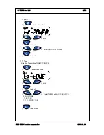
Page 7: ...td 7 26 3 Contact list 1 to enter Menu Mode 2 or to until 3 to select 4 or to scroll list 5 to exit 4 Status call list 4 1 Making STATUS call 1 to enter Menu Mode 2 or to until 3 to select 4 or to scr...

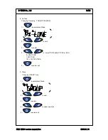
Page 8: ...nual doc 2006 01 10 E TECH Co Ltd 8 26 4 2 Make STATUS Message 1 to enter Menu Mode 2 or to until 3 to select 4 or to scroll list 5 to SELECT 5 Lone work 1 to enter Menu Mode 2 or to until 3 to select...

Page 9: ...o enter Menu Mode 2 or to until 3 to select 4 or to select HIGH LOW POWER 5 to select 7 Tx Tone Selecting Transmitting TONE CTCSS DCS 1 to enter Menu Mode 2 or to until 3 to select 4 or to Select TONE...

Page 10: ...ceiving TONE CTCSS DCS 1 to enter Menu Mode 2 or to until 3 to select 4 or to select TONE either CTCSS or DCS 0 NON TONE 1 38 CTCSS 101 183 DCS TONE 5 to select exit 9 Group Changing GROUP Tone 1 to e...

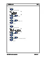
Page 11: ...c 2006 01 10 E TECH Co Ltd 11 26 10 Beep on off 1 to enter Menu Mode 2 or to until 3 to select 4 or to select on off 5 to select 11 Key lock 1 to enter Menu Mode 2 or to until 3 to select 4 or to sele...

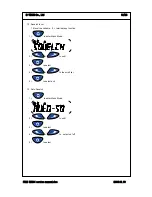
Page 12: ...d 12 26 12 Squelch level 16 level is available 0 terminate sq function 1 to enter Menu Mode 2 or to until 3 to select 4 or to the scroll list 5 to select exit 13 Auto Squelch 1 to enter Menu Mode 2 or...

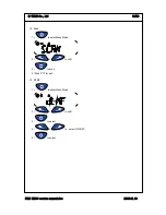
Page 13: ...service manual doc 2006 01 10 E TECH Co Ltd 13 26 14 Scan 1 to enter Menu Mode 2 or to until 3 to scan 4 Push PTT for exit 15 DTMF 1 to enter Menu Mode 2 or to until 3 to select 4 or to select ON OFF...

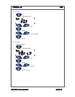
Page 14: ...10 E TECH Co Ltd 14 26 16 Vox on off 1 to enter Menu Mode 2 or to until 3 to select 4 or to select ON OFF 5 to select 17 Vox Level 16 level is available 1 to enter Menu Mode 2 or to until 3 to select...

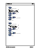
Page 15: ...doc 2006 01 10 E TECH Co Ltd 15 26 18 Auto Vox 1 to enter Menu Mode 2 or to until 3 to select 4 or to select ON OFF 5 to select 19 Priority Scan 1 to enter Menu Mode 2 or to until 3 to select 4 or to...

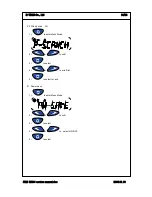
Page 16: ...006 01 10 E TECH Co Ltd 16 26 20 Priority scan CH 1 to enter Menu Mode 2 or to until 3 to select 4 or to scroll list 5 to select for exit 21 Power save 1 to enter Menu Mode 2 or to until 3 to select 4...

Page 17: ...al doc 2006 01 10 E TECH Co Ltd 17 26 22 Talkaround 1 to enter Menu Mode 2 or to until 3 to select 4 or to select ON OFF 5 to select 23 Password 1 to enter Menu Mode 2 or to until 3 to select 4 or to...

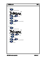
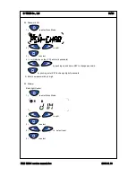
Page 18: ...to until 3 to select 4 will display on the LCD enter old password or by pushing up and down KEY to change password by pushing enter KEY to change digit of password 5 Enter new password by 4 digit 25 D...

Page 19: ...doc 2006 01 10 E TECH Co Ltd 19 26 26 Scramble 1 to enter Menu Mode 2 or to until 3 to select 4 or to select ON OFF 5 to select 27 Status call Send 1 to enter Menu Mode 2 or to until 3 to select 4 or...

Page 20: ...2006 01 10 E TECH Co Ltd 20 26 28 Misscall List Delete 1 to enter Menu Mode 2 or to until 3 to select 4 or to select ON OFF 5 to select 29 Radio Reset 1 to enter Menu Mode 2 or to until 3 to select 4...

Page 21: ...iable call 1 to enter Menu Mode 2 or to until 3 to select 4 or to select 1 2 3 A B C D E 5 to select 31 Mic Sensitivity Level Mic Gain Control 1 to enter Menu Mode 2 or to until 3 to select 4 or to se...

Page 22: ...TOR DESCRIPTION Connection Pin NO Function Remark GND Ground GND CPU_INT_PTT Push To Talk GND Enable 5V Internal 5 Volt Regulator 5 Volt FLAT_AUDIO_IN OUT Constant Audio Signal Level S W_BATT Switched...

Page 23: ...tall the vehicle antenna external to a metal body vehicle in accordance with those requirements 2 Roof top For optimum performance and compliance with RF Energy Safety standards mount the antenna in t...

Page 24: ...springs shift levers trunk and hood lids exhaust pipes etc in close proximity to the antenna can cause severe receiver interference 5 3 Antenna Installation Procedure 1 Mount the antenna according to...

Reviews: