

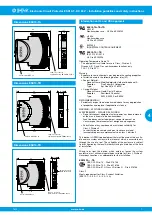


Electronic Circuit Protector ESX10-T.-DC 24 V
Electronic Circuit Protector ESX10-T.-DC 24 V
www.e-t-a.de
2
1822
4
Technical data (T
amb
= 25 °C, U
B
= DC 24 V)
Free-wheeling diode
external free-wheeling diode
recommended for inductive load
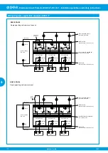
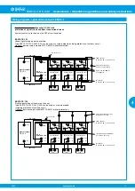
Parallel connection of several load outputs
not permitted
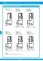
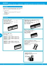
Signal output F
ESX10-T.-101/-102
Electrical data
potential-free auxiliary change-over
contact max. DC 30 V/0.5 A min. 10 V/10 mA
Standard condition
U
B
is applied and switch S1 is ON and
LED green
no overload, no short circuit
OFF condition, LED off
l
device switched off (switch S1 to OFF)
l
no operating voltage U
B
Fault condition LED orange overload conditions > 1.1 times I
N
until
electronic disconnection
Fault condition LED red electronic disconnection after
overload or short circuit
ESX10-TB-101
single signal, make contact
contact open, terminal 13-14
ESX10-TB-102
single signal, make contact
contact closed, terminal 11-12
Error
signal output is in fault condition, if
l
there is no operating voltage U
B
l
the ON/OFF switch S1 is in OFF posi-
tion
l
the red LED is lighted
(electronic disconnection)
Status output SF
ESX10-T.-114/-124/-127
Electrical data
plus switching signal output,
connects U
B
to pin 23
Current ratings: DC 24 V/max. 0.2 A
(short circuit proof)
The status output is connected internally
with a 10 kOhm resistor against 0 V.
Status OUT
ESX10-TB-114/-124 (signal status OUT),
at U
B
= + 24 V
+ 24 V = S1 is ON, load output connected
0 V = S1 is ON, load output locked
and/ or switch S1 is OFF
red LED lighted
Status OUT
ESX10-TB-127 (signal status OUT
inverted), at U
B
= + 24 V
+ 24 V = S1 is ON, load output locked
red LED lighted.
0 V = S1 is ON, load output connected
and/or switch S1 is OFF.
OFF condition
0 V level at status output whenever:
l
switch S1 is in ON position, but device
is still in ON delay
l
switch S1 in OFF position, or control
signal
OFF, device is switched off
l
No operating voltage U
B
Reset input RE
ESX10-T.-124/-127
Electrical data
voltage max. DC 32 V
High > DC 8 V ≤ DC 32 V
Low < DC 3 V > 0 V
current consumption typically 2.6 mA
(DC 24 V)
min. pulse duration 10 ms
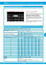
Operating data
Operating voltage U
B
DC 24 V (18...32 V)
Current ratings I
N
fixed rating:
Types ESX10-TA-... and -TB-...:
0.5 A, 1 A, 2 A, 3 A, 4 A, 6 A, 8 A, 10 A, 12 A
adjustable current ratings:
type ESX10-TD-...:
[0.5 A/1 A/2 A], [2 A/4 A/6 A], [6 A/8 A/10 A]
Standby current I
0
in ON condition: typically 20 ... 30 mA
depending on signal output
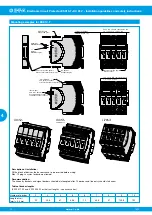
Visual status
l
multicoloured LED:
indication via
green:
- device is ON (S1 = ON)
- load circuit/Power-MOSFET connected
orange:
- overload or short circuit until
electronic
disconnection
red:
- device switched OFF electronically
- load circuit/Power-MOSFET
disconnected
- undervoltage (U
B
< 8 V)
- after switch-on until the end of the
switch-on delay period
OFF:
- manually switched off (S1 = OFF) or
device is dead-voltage
l
status output SF (optional)
l
potential-free signal contact F (optional)
l
On/off position of the switch S1
Load circuit
Load output
power MOSFET switching output
(plus switching)
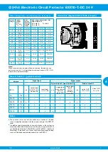
Overload disconnection (OL) typically 1.1 x I
N
(1.05...1.35 x I
N
)
Short circuit current I
K
active current limitation with
I
Limit
= typically 1.8/1.5/1.4/1.3 x I
N
,
I
Limit
depending on I
N
(typically I
Limit
- values, see table 1)
Trip times
see time/current characteristic
Trip thresholds/trip
1. threshold:
times (t
1
, t
2
) at overcurrent at I
load
> typically 1.1 x I
N
...I
Limit
:
(I
Limit
see table 1)
t
1
= typically 3 s
2. threshold:
at I
load
= I
Limit
:
t
2
= typically 100 ms...3 s
Temperature disconnection internal temperature monitoring with
electronic disconnection
Low voltage monitoring
of load output
with hysteresis, no reset required
load “OFF” at U
B
< 8 V
Switch-on delay
typically 0.5 s
t
Start
after each ON operation, after reset and
after applying of U
B
Disconnection of
electronic disconnection after
load circuit
overload/short circuit
Technical data (T
amb
= 25 °C, U
B
= DC 24 V)


