background image


18 

6. CIRCUIT BREAKER  
FUNCTIONALITY 

The last third of the overview page displays addi-
tional information and functions for the selected cir-
cuit breaker. Three different tabs can be selected on 
the left-hand side. These are explained below: 


6.1 Parameter 

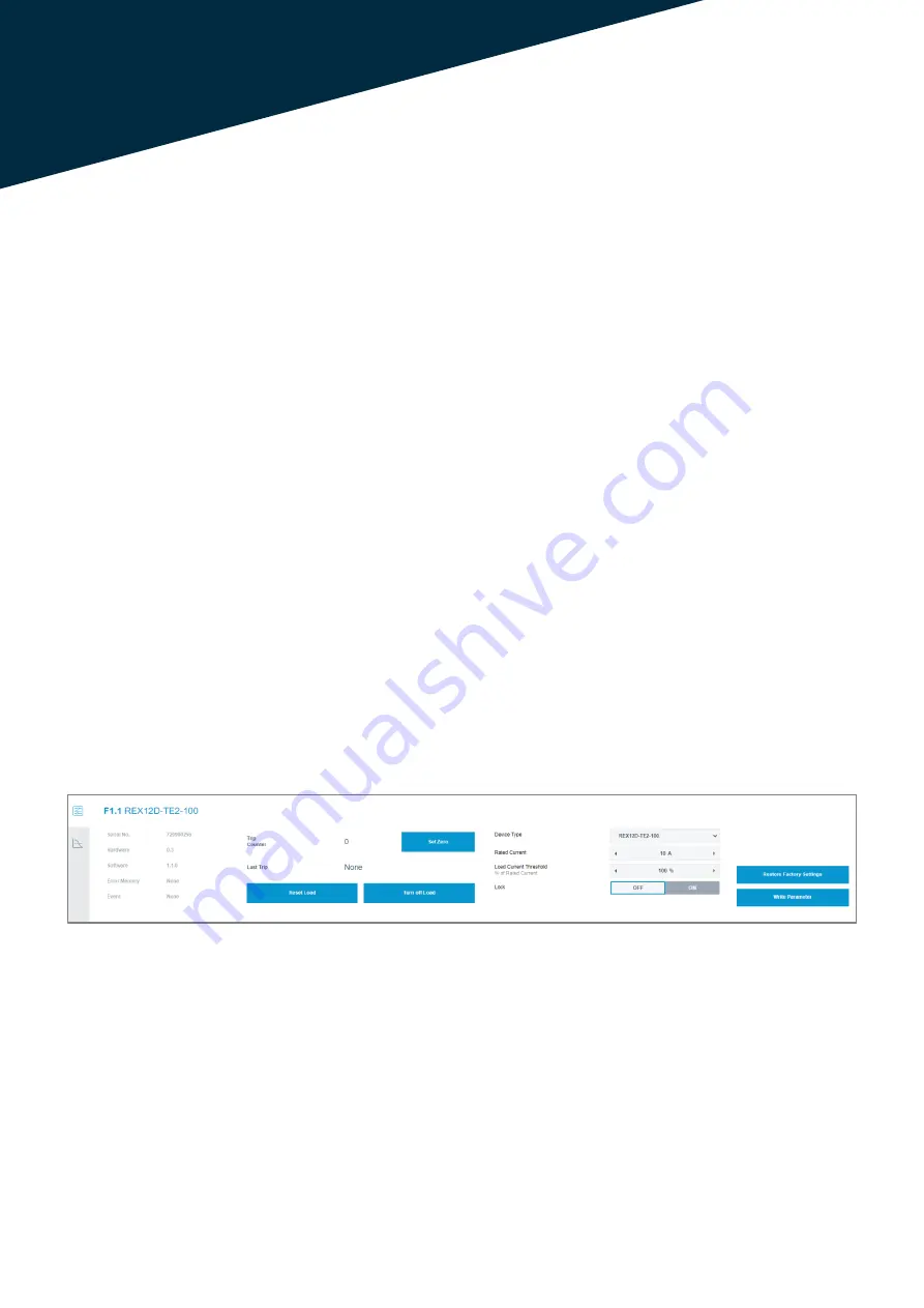
The first tab displays general information about the 
circuit breaker, such as the serial number and the 
hardware and software version. Furthermore, the last 
error reason can be read out. 

The possible parameters that can be set have al-
ready been explained in the "Batch Edit De-vice" 
function. The different input fields can be adjusted by 
the integrated arrow keys. If the required value is 
reached, the new setting can be loaded into the de-
vice via the "Write Parameter" button. 

The "Restore Factory Settings" button resets all pa-
rameters to the factory settings.  


The "Lock" selection option blocks switching the cir-
cuit breaker off or on from the software. 

As soon as the function is set to status "OFF", the cir-
cuit breaker can be switched. As soon as the circuit 
breaker is switched off from the software, the hard-
ware LED at the channel shows the colour orange. 


Attention: 
The role of the logged in account has to be checked. 
The differences between the Admin and the User 
mode are explained in chapter 4.1.3.4. 

In addition, the function for resetting a circuit breaker 
and switching it on and off is not available with a con-
nected fieldbus interface. The PLC software has a 
higher priority. 

Furthermore, control and writing via the webserver 
can be deactivated via the PLC software (Configura-
tion data of the CPC12 - Byte 0 Bit 0)! 


Image 25: General information and adjustable parameters of the circuit breaker 

Summary of Contents for ControlPlex CPC12

Page 1: ...1 20 INSTRUCTION MANUAL INSTRUCTION MANUAL ControlPlex CPC12 bus controller Webserver...

Page 2: ...Connection with the Webserver 6 4 Webserver Functionality 9 4 1 Menu Bar 9 4 1 1 User Management 9 4 1 2 CPC Info 10 4 1 3 Configure 10 4 1 4 Commands 14 4 2 Status Bar 16 5 Circuit Breaker Overview 1...

Page 3: ...e Qualified personnel This user manual must exclusively be used by quali fied personnel who are able based on their training and experience to realise arising problems when handling the product and to...

Page 4: ...the field bus interface the data are also made available to the superordinate control systems E T A s REX12D system in combination with the CPC12 bus controller was designed specifically for the requ...

Page 5: ...5 5 Image 2 Setup of the REX12D system in combination with the CPC12 bus controller...

Page 6: ...set to the standard IP range 192 168 1 XXX for example 192 168 1 254 1 Under Windows Settings the submenu Network and Internet is selected 2 Clicking on Change adapter options opens the Network conne...

Page 7: ...Edge browser was used In addition the browser variants Chrome and Mozilla Firefox in the latest versions are possible Only these variants are checked and available for the webserver All other browser...

Page 8: ...8 After a successful connection the following overview page of the ControlPlex system is displayed Image 7 Overview page of the ControlPlex system...

Page 9: ...management Depending on the selection of a function a pop up window appears with the request to enter the username and password the ControlPlex system In addition an overview of the supply voltage and...

Page 10: ...on No admin rights needed The product ID the serial number as well as the hardware and software version are displayed This in turn includes various functionalities which are described below 4 1 3 2 Ne...

Page 11: ...e language setting is also reset to English and the user management is reset The function is only possible in Admin mode 4 1 3 4 Edit Users After selecting the function a new window opens with the ove...

Page 12: ...e Update After selecting the Firmware Update function an Explorer window opens to access the location of the firmware file The latest firmware updates are availa ble in the download portal of the Cont...

Page 13: ...Box The function Back to Box resets the CPC12 to the factory settings All configurations are set to default The function is only possible in Admin mode Without a reload the changes will not take effe...

Page 14: ...e Lock function of the circuit breaker is set to the OFF status the function is only possible in Admin mode and without connection to the fieldbus 4 1 4 2 Reset Devices By selecting this function afte...

Page 15: ...ith an overview page of all configured parameters First a pop up window asks whether the existing parameters of the current system should be loaded Download Config an already saved configuration file...

Page 16: ...can be evaluated immediately using the boxes in the area Device This box is di vided into two areas By clicking on these areas it is also possible to navigate the circuit breaker overview page to the...

Page 17: ...urrent as well as different status messages The upper rectangle contains the currently set cur rent rating Depending on the recent switching state or message the box changes its colour Gray Off Green...

Page 18: ...n The Restore Factory Settings button resets all pa rameters to the factory settings The Lock selection option blocks switching the cir cuit breaker off or on from the software As soon as the function...

Page 19: ...breaker are listed Instruction manual Bus Controller CPC12 EN Ref number Y31395702 Index Issue 03 2023 All rights reserved In addition calculated values for the average value in each case are listed N...

Page 20: ...cx E T A Elektrotechnische Apparate GmbH Industriestra e 2 8 90518 Altdorf Tel 49 9187 10 0 Fax 49 9187 10 397 E Mail info e t a de global e t a com Technical changes misprints and errors reserved Web...

Reviews: