8
E-flite Rhapsody 25e ARF Assembly Manual
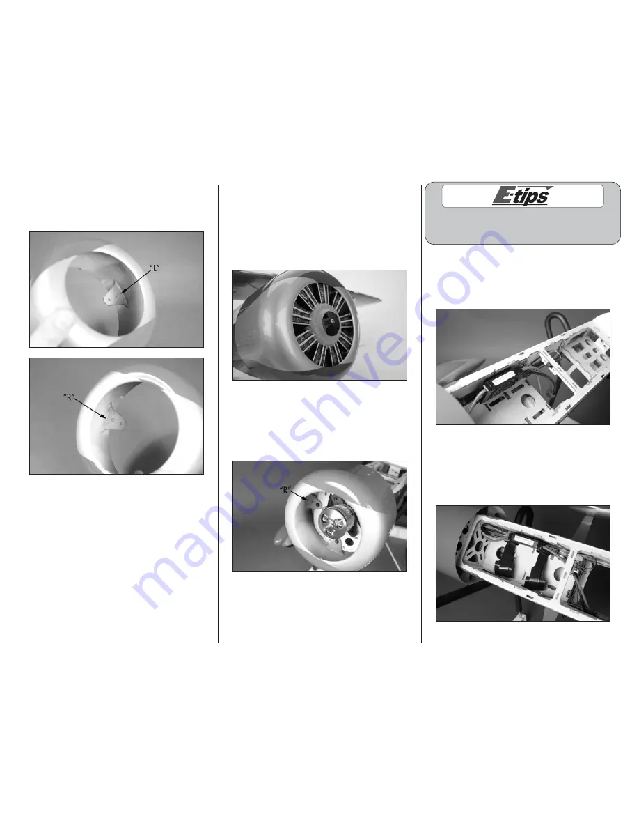
4. The tabs on the cowl have markings so the
cowl can be oriented on the firewall. The L and R
indicate the left and right as viewed as if sitting in
the cockpit.
Note
: We used the following colors when
painting the engine: Make sure to paint the
motor before gluing it in the cowling.
Rocker Shafts – Aluminum
Engine Cylinders – Black
Plug Wires – Yellow
Center Crankcase – Light Gray
5. (Optional) Use a hobby knife and rotary tool to
remove the area in the center of the dummy radial
engine. Use a hobby knife to remove the area
between each of the cylinders to allow cooling air
to pass through the cowling and over the motor.
Use 6-minute epoxy to glue the dummy radial
engine inside the cowling. Use the following colors
to paint the dummy radial engine.
6. Route the motor leads through the firewall and
into the fuselage. Use four 4-40 x 3/8-inch socket
head screws and four #4 washers to attach the
cowl to the firewall. Use a 3/32-inch ball driver to
tighten the screws. The R for the right side of the
cowl can be seen in the photo below.
Matching the colors between the ESC and motor
when they are connected results in the correct
motor direction if using all E-flite components.
7. Connect the leads from the motor to the speed
control. Use hook and loop tape to secure the
speed control in the fuselage. Mount the speed
control switch in the fuselage using the hardware
provided with the speed control.
8. Insert the hook and loop straps through the battery
tray as shown. The battery will be installed later in
the manual after the wings have been installed, but
installing the strap now will be much easier. Apply
a strip of hook and loop tape on the battery tray to
keep the battery from sliding fore or aft on the tray.


