


14
E-flite Advance 25e ARF Assembly Manual
Always use threadlock on metal-to-metal fasteners.
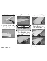
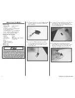
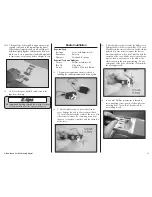
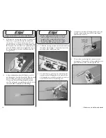
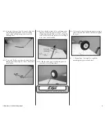
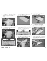
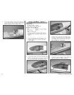
5. Position the steering arm in the nose gear mount.
Slide the nose gear wire through the mount and
steering arm so it is flush with the top of the nose
gear mount. The steering arm will angle away from
the firewall so the nose wheel can operate properly.
Use a #1 Phillips screwdriver to tighten the screw in
the steering arm so it rests on the flat area on the
nose gear wire.
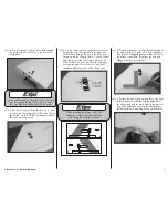
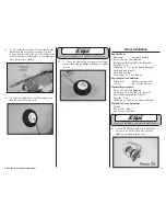
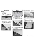
6. Use a hobby knife with a #11 blade to cut a 1/4-
inch (6mm) piece from the silicone tube. Slide the small
piece of tubing on a nylon clevis. Thread the clevis
12-turns on a 24-inch (610mm) threaded pushrod
wire. This will provide enough thread in the clevis to be
secure and allow for adjustment of the linkage.
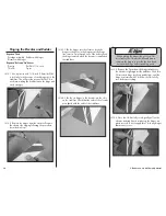
Use the rudder trim on the radio to trim the
model in flight. If the model does not track
straight on the runway, adjust the clevis on
the steering linkage. Do not use the rudder
trim to correct the steering on your model.
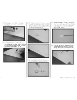
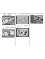
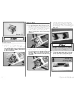
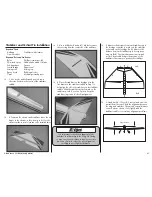
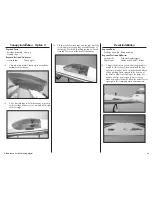
7. Slide the steering pushrod wire into the tube from
the inside of the fuselage. Connect the clevis to the
outer hole of the rudder servo horn.
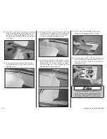
8. Center the nose gear wire. The axle (where the
wheel mounts) will be parallel to the firewall. Use
a felt-tipped pen to mark the pushrod wire where it
crosses the outer hole of the steering arm.
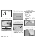
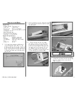
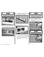
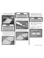
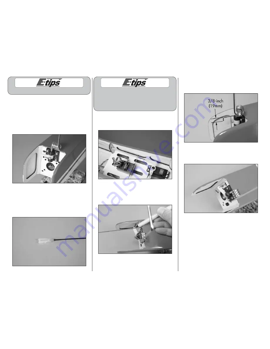
9. Use pliers to make a 90-degree bend in the wire.
Use side cutters to trim the wire 3/8-inch (9mm)
past the bend as shown.
10. Insert the wire through the outer hole in the
steering arm. You may have to disassemble the nose
gear assembly to fit the wire through the hole.