E+E Elektronik EE680 User Manual Download Page 14

14

User Manual EE680 

Air Velocity and Temperature Sensor for Laminar Flow

5.4.6  Optical Status Indication for Probe and Laminar Flow

Menu Item

Configurable Items

Optical status 

indication

Status indication active or inactive

Selection between error indication and laminar flow status
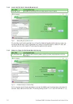
Fig. 15 

Selection of optical status indication mode

The status of the laminar flow and the probe is indicated optically by the LED ring embedded in the 

probe body. 

The user can adjust the behaviour of the optical status indication and choose from the 

following options:


ƒ

Status indication is active / inactive

If active, two status indication modes are selectable :


ƒ

Error indication - probe status: normal operation 

(GREEN)

 / failure 

(RED FLASHING)


ƒ

Laminar flow status: measurand within 

(GREEN) 

/


out of a given range

 (YELLOW FLASHING) 

+

 Error indication - probe status: normal operation 

(GREEN)

 / failure 

(RED FLASHING)


The table below summarizes the meaning of LED indication:

Colour

Function / Failure

None

No suitable supply, status indication disabled

GREEN

Probe status: normal operation, no failure 

Laminar flow status: measured value in range

YELLOW FLASHING

Probe status: normal operation, no failure 

Laminar flow status: measured value out of range

RED FLASHING

Probe status: failure, return sensor for investigation

Tab. 3 

Meaning of LED ring light characteristics

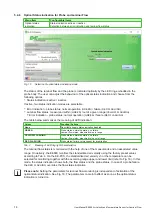
The laminar flow status is monitored with the help of one of the measurands and an associated value 

range. On delivery, the EE680 monitors the standardized air velocity using the factory preset values 

according to Tab. 4. Via the EE-PCS, the standardized air velocity vn or the temperature can be 

selected for monitoring together with the according range upper and lower limit (refer to Fig. 16). In this 

mode, the status indication shows both, the flow status and the probe status. In case of a probe failure, 

the 

RED FLASHING

 overrides the flow status indication.
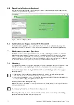
Please note:

 Setting the parameters for laminar flow monitoring is independent of activation of the 

optical status indication. See Fig. 16: The parameters come into effect as soon as the optical status 

indication is turned on.

Summary of Contents for EE680

Page 1: ...BA_EE680 v1 0 Modification rights reserved User Manual EE680 Air Velocity and Temperature Sensor for Laminar Flow...

Page 2: ...equipment has been tested and found to comply with the limits for a Class A digital device pursuant to part 15 of the FCC Rules These limits are designed to provide reasonable protection against harmf...

Page 3: ...asurement 12 5 4 3 Reference Values for the Standardized Air Velocity 12 5 4 4 Digital Interface Configuration 13 5 4 5 Selection between Analogue and Digital Output 13 5 4 6 Optical Status Indication...

Page 4: ...ng element is sensitive to electrostatic discharge ESD avoid touching the sensing element whenever possible appropriate protective measures should be taken when touching it Installation electrical con...

Page 5: ...or start up a device supposed to be faulty Make sure that such devices are not accidentally used by marking them clearly as faulty A faulty device may only be investigated and possibly repaired by qu...

Page 6: ...ut or on the RS485 interface with Modbus RTU protocol The analogue output and other settings can be configured with the EE PCS 3 2 Dimensions L according to ordering code 9 7 0 4 8 0 3 89 3 5 12 0 47...

Page 7: ...g HA010705 Connection cable HA010819 820 821 1 Supply voltage 24 V DC 20 Class III brown 2 Analogue out 2 or RS485 D Data white 3 GND blue 4 Analogue out 1 or RS485 D Clock black 5 Configuration pin g...

Page 8: ...r For convenient handling the cable should extend 5 cm 2 in from the flange and there should be enough space for it behind the flange Connect the sensor with the M12 connector Insert the sensor into t...

Page 9: ...y configuration by the user The EE680 factory setup corresponds to the type number ordered Please refer to the data sheet at www epluse com EE680 The user can change the factory setup with the help of...

Page 10: ...ge from www epluse com Configurator Please refer also to chapter 5 4 4 2 Modbus protocol in the register 60001 0x00 and 60002 0x01 See Modbus Application Note AN0103 available at www epluse com EE680...

Page 11: ...s from 0 3 Standardized air velocity vn at standard conditions factory setup Tn 23 C 73 F pn 1 013 25 hPa 14 7 psi settable via EE PCS 4 Examples For scale 100 the reading of 2550 means a value of 25...

Page 12: ...surement of the standardized air velocity is stopped below the switch off value and resumed as soon as the switch off value plus the hysteresis is exceeded 5 4 3 Reference Values for the Standardized...

Page 13: ...ital interface settings The interface parameters for Modbus communication can be changed Fig 13 shows the recommended values they are set in the factory 5 4 5 Selection between Analogue and Digital Ou...

Page 14: ...Failure None No suitable supply status indication disabled GREEN Probe status normal operation no failure Laminar flow status measured value in range YELLOW FLASHING Probe status normal operation no f...

Page 15: ...0 36 m s 70 9 ft min Range upper limit 0 54 m s 106 3 ft min Tab 4 Factory default values for laminar flow monitoring Fig 17 Response time setting The fastest response time possible is 1 5 s with ave...

Page 16: ...oint vn T adjustment With 2 point adjustment precise measuring results can be obtained over the entire vn T measuring range The more complicated 2 point adjustment procedure is preferable to 1 point a...

Page 17: ...17 User Manual EE680 Air Velocity and Temperature Sensor for Laminar Flow 6 2 Velocity Adjustment Fig 18 vn 1 point adjustment...

Page 18: ...18 User Manual EE680 Air Velocity and Temperature Sensor for Laminar Flow Fig 19 vn 2 point adjustment...

Page 19: ...19 User Manual EE680 Air Velocity and Temperature Sensor for Laminar Flow 6 3 Temperature Adjustment Fig 20 T 1 point adjustment Fig 21 T 2 point adjustment...

Page 20: ...sensing head may be cleaned as described below and the device may be re adjusted as described in chapter 6 7 1 Cleaning The EE680 was optimized in means of used materials probe and sensor head made o...

Page 21: ...lth of our employees at any time 7 3 Repairs Repairs may be carried out by the manufacturer only The attempt of unauthorized repair excludes any warranty claims 7 4 Error Indication on the Analogue Ou...

Page 22: ...Accessories data sheet Modbus configuration adapter HA011018 E E Product Configuration Software EE PCS free download www epluse com configurator Protection cap M12 female connector HA010781 Protectio...

Page 23: ...ts 1 Modbus address 68 General Power supply Class III 24 V DC 20 Current consumption typ 30 mA Electrical connection M12x1 5 poles stainless steel 1 4404 Protection rating IP65 Enclosure material Stai...

Page 24: ...lin 69130 Ecully Tel 33 4 74 72 35 82 E mail info epluse fr E E Elektronik Germany Sch ne Aussicht 8 C 61348 Bad Homburg Tel 49 6172 13881 0 E mail info epluse de E E Elektronik Italy Via Alghero 17 1...

Reviews: